Last time around we explored setting gain in inverting and non-inverting configurations, and how phase affects performance. This time, we embrace failure, in theory.
We learn more when things go wrong, and an unstable amplifier could be classed as having gone wrong. Instead of waiting like lambs for the (ahem) learning experience to find us, why not intentionally break an amplifier?
Make it Fail!
Why does a 180° lag where the gain is well below 0dB matter? In the cases presented so far, it doesn’t. When using amplifiers for filtering signals, reactive components (i.e. inductors or capacitors) are added to the circuit; in that case, it might. How about a series inductor in the feedback loop?
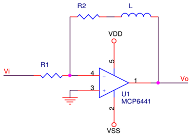
Putting an inductor in the feedback loop is unusual. In this case it’s an exercise and would not normally be done; the point here is to see if the amplifier can be deliberately made to oscillate. Renaming R2 to the more generalized Zfeedback, and carefully choosing an inductance to illustrate the point:
![]()
With a series inductor L:
![]()
Where f is frequency in Hz, and j is an imaginary number (yes it’s normally denoted with an i but i already represents current, so j it is).
Getting back to that careful choice of inductance:
![]()
This choice makes the quadrature (reactive) component of impedance equivalent to the in-phase (resistive / non-reactive) component at 100Hz, the reason for which should be come clearer as we go:
![]()
Simplifying:
![]()
What does this do to gain? Well, this:
![]()
Gain is recognizable as the previous inverting configuration, but now has an extra frequency-dependent term. It should be obvious that above 100Hz the impedance is mostly reactive; less than 100Hz, mostly resistive. Note also that gain increases unbounded with frequency…until the Gain Bandwidth limit is reached.
To illustrate the point, some plots showing behaviour of gain and phase should help:
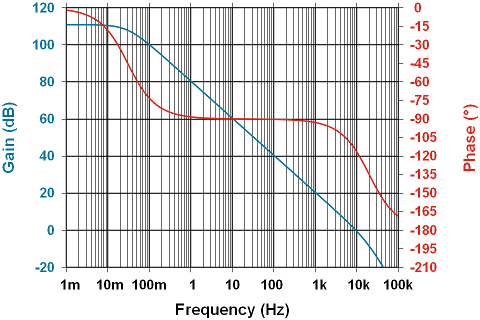
Above is a reboot of the previously shown MCP6441 gain/phase plot, however in this case the effect of the extra pole on gain is visible. Note that for frequencies greater than at unity gain (0dB / ~10KHz) the gain begins to roll off at 40dB/decade rather than 20.
The phase of the amplifier as shown above is -90°. This means the voltage at Vo is lagging 90° behind the voltage between the non-inverting & inverting pins, or ΔV. For instability to occur, we’d need to affect the phase difference only from Vo to ΔV.
Below is the closed loop feedback gain and phase based on the equations discussed above.The phase angle crosses 45° at 100Hz, just as expected:
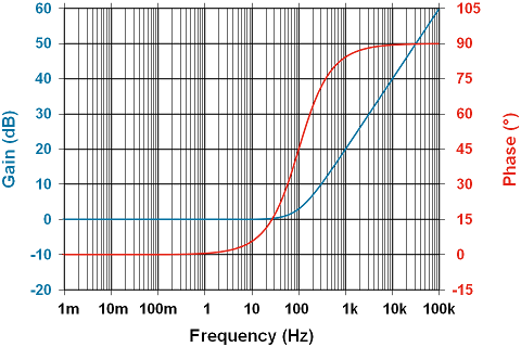
Note that as the reactive component’s impedance increases, it begins to push the phase in a positive direction relative to Vi. As the inductance begins to dominate the impedance, and hence add its 90° of phase shift back into the mix, doesn’t this make the amplifier more stable? Vo is now, in theory at least, in phase with the inputs, right? Not exactly.
Since the positive input (pin 3) is grounded, and we’re concerned with the difference in phase between ΔV (Vpin3 – Vpin4) and Vo, this means the difference is well, upside-down. So, that 90° that the inductor begins to contribute, is actually pushing the phase difference towards instability. This is bad, which is good, since we’re trying to push it over the edge.
Because this is unstable feedback, any noise with a frequency component near the point of resonance will be amplified and fed back into the inputs, getting bigger with each cycle. This will be limited by the supply voltage in the end, but it should be clear this circuit will produce oscillations with no regard for what’s happening at Vi.
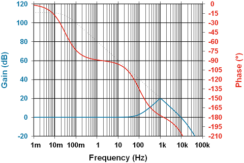
The figure above shows gain with the boundary of open-loop gain and the phase of the amplifier itself taken into account. Note that the phase is settling in at around 90° in 0.1-10Hz range, but then begins to shift extremely rapidly as both the 2nd pole in the amplifier and the zero from the inductor contribute. This is a nearly perfect storm. Because the impedance in the feedback loop is increasing as the 180° phase boundary is approached, the maximum amount of gain is being applied at the most unstable point. Any gain greater than 0dB where phase is 180° will oscillate.
A Couple of Side Notes
Peripherally related to closed loop control and stability are the control-system concept of Rate of Closure, and the not-so-common Decompensated Op-Amp.
Rate of Closure
There’s a slightly less subtle hint of instability. The gain curve can be seen to increase from 0dB/decade to 20dB/decade as frequency rises above about 10Hz; the open-loop gain curve is decreasing at 20dB/decade in the same frequency range. The slope at which the closed loop gain curve intersects the open loop gain curve is called the rate of closure, and for stability must be no greater than 20dB/decade. In this case, it’s roughly: 20dB/decade – -20dB/decade = ~40dB/decade. This is bad, which in this case is good…you get the idea.
Way earlier in this post, it was noted that the extra pole might be of some significance. If the amplifier is running at unity gain, and the closed loop gain curve hits the open loop curve at a point where the amplifier is beginning to decrease gain at a rate higher than 20dB/decade, say a slope of -23dB/decade for example, the amplifier can actually go unstable. This is why a little care is required when using a unity-gain configured amplifier. This configuration has marginal stability at frequencies around the gain-bandwidth product.
Compensated vs. Decompensated
Some amplifiers are actually not “unity gain stable”, meaning if their output is fed back to their inverting terminal with no gain setting resistors in place, they will oscillate. Why on earth would anybody want that?
There are other properties of amplifiers that limit performance. One parameter that goes hand-in-hand with bandwidth is slew-rate. Slew rate is the maximum rate of change of the amplifier’s output. The higher the slew-rate, the faster the amplifier. This makes sense, and ties back into the unity-gain bandwidth problem. More gain means less bandwidth because the amplifier must swing much faster to replicate a higher amplitude signal. If the peak-to-peak voltage is higher, the slope of the voltage curve will be much steeper, and might bump into that testy slew-rate. So, a high slew rate is often a desirable thing.
Op-amps are almost always “compensated.” That means they have those internal poles to keep the amplifier gain less than unity when phase margin approaches 0°. The penalty for this is reduced slew rate, and more current required to push the amplifier’s performance when hampered by these internal poles.
Some amplifiers are “decompensated.” This means they lack those poles and as a result, at unity gain, are not stable. Slew rate is however, much higher, current consumption lower, and cost usually unaffected. These are desirable things. The price is there is a minimum amount of gain at which the amplifier can reliably operate. Working with decompensated amplifiers is hence, a more advanced topic.
So we have a design that should oscillate and behave a little unpredictably, but the value required for inductance is impractically large. We have also scratched the surface on Rate of Closure and Decompensated Amplifiers.
Next time around, we’ll try making this work with a higher-bandwidth amplifier (an LF353) and readily available passive components.