Last time we looked at low pass filters, this time high-pass; it’s opposite day. We also take a brief look at capacitor types, as they are critically important to filter design.
High Pass
High-pass filters are encountered a little less frequently than the basic first-order low-pass, but they do have utility; for instance, blocking DC and filtering out AC line noise in audio circuits. We’ll stick to the inverting mode in this case.

Continuing as previously with frequency-domain analysis, as it makes the math algebraic; don’t be scared, no differential equations will be introduced, yet. The gain equation breaks down as follows:
![]()
Converting to a magnitude with an angle, and leaving the magnitude negative since it is inverting:
![]()
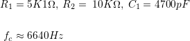
As before, we need to choose fc, and select some values. Since this is just a straight up exercise, we’ll pick values first, and see where we end up. We are cheating because we’re using much the same values as the previous post used for low-pass:
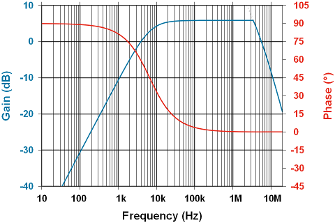
So on a Bode plot, we find the amplitude and phase behave exactly as calculated; note the apparent low-pass characteristic at the high end is due to the amplifier’s open-loop gain curve.
Similar to the low-pass filter analysis, we’ve set the this up as follows:
- Amplifier: LF353N
- Gain: 2:1, fc ≅ 6640Hz
- Supply voltage: ±15V
- Input: sine wave, 7.5Vpp, logarithmic sweep from 10Hz to 10MHz, 120mS per sweep
- Horizontal axis: 10mS/major division, each 2 divisions is a decade increase in frequency
- Vertical axis: 1V/major division
- note this is linear, not logarithmic; the axis is different from the above plot
- Sync: External sync pulse from signal generator
- Persistence: none; the shape fills in nicely anyway.
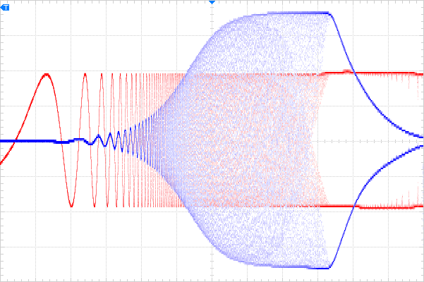
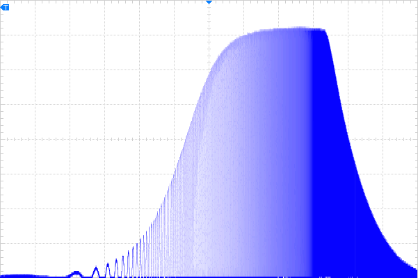
The red curve above is the input; blue is output. This shows full signal, and a close look reveals the output sinusoid is indeed leading the input as frequency increases. Sliding that down to the bottom of the display, we get something not completely unlike a Bode plot, if the linear vertical axis can be excused.
We really shouldn’t rely on the open-loop gain curve to limit the top-end performance, so we’ll address that next post; mean time, as promised, a few words about capacitors.
Capacitor Notes
Capacitors are the heart of most filters, so understanding why one type is better than another is important.
The above configuration can be a little tough on the filter capacitor if the signal source has extraordinarily low impedance. Capacitors in reality are not ideal. While they theoretically have no resistance or inductance, in reality they do. This means the capacitor itself will dissipate some power, but even if it were ideal, a high-current signal source will be heavily taxed by what is effectively a dead-short for some frequencies.
Capacitors use different dielectric materials depending on the amount of capacitance, voltage rating, and intended use. Though there are many types, we’ll limit the exploration to what’s useful in filter capacitors.
Ceramic
For smaller, closer to ideal capacitors, ceramic capacitors are widely available, however there are myriad types, each with unique features and benefits. It’s also a highly competitive and evolving market; new types are appearing all the time. Dielectrics are usually specified by a three digit code: NP0, X5R, X7R, Y5V, Z5U; all are readily available. What to choose? Usually these codes have to do with stability.
The letters, of course, all mean something. There are two major classes: Class 1, and Class 2; crazy complicated. Ultimately, we want a class 1 capacitor wherever we can get one, but we’ll go over class 2 first and why it’s a second-place choice.
In class 2 dielectrics, the first letter, X,Y,Z, translates to the minimum operating temperature: -55°C, -30°C,+10°C. Applications that will operate below 10°, therefore, should not use capacitors with a Z in their first letter. The second digit is the high temperature; higher numbers mean higher temperatures: 5 & 7 translate to +85°C & +125°C respectively. The final digit is the typical tolerance over temperature range: R = ±15%, U = +22/-56%, V = +22/-82%; so choose R if a class 2 dielectric is being used in a filter. This means Z5U and Y5V, though they offer amazing capacitance per unit volume, are not good choices. Really, class 2 is chosen only when there’s an overriding factor, like insufficient space, or a tight budget.
One additional “feature” of X, Y, and Z series capacitors is they are subject to piezoelectric coupling. This means mechanical vibrations can be turned into electrical signals by the capacitor, and coupled into the circuit. In an audio circuit this can be a frustrating source of noise. For this reason, these dielectrics should be avoided for filters.
Class 1 capacitors constructed width NP0 dielectric are a better choice for two reasons: they have the most stable temperature coefficient, typically 0±30ppm/°C; and, they have no piezoelectric sensitivity. This should be a first choice, unless that little bit of extra performance is needed; in which case, film capacitors may have a slight edge.
Film
Film capacitors are a class on their own. There are several different types, polyester, polypropylene, polycarbonate… basically they’re all poly-somethings, plastics of different types. Of them, polypropylene offers a very stable, high Q factor capacitor which is excellent for filters and resonant circuits. They are a little bulky, so can only be used where space is available. They are available in surface mount, but they can be a little tough to work with as they’re made of plastic, and will encounter a soldering iron, or reflow oven. If you have to solder these by hand, sharpen your skills, and be quick with the iron.
Wrapping up, for a first order filter, the math builds on previous analysis, and the behaviour matches the mathematical model quite nicely. A brief review of the types of capacitors best suited to filters shows film is best if space permits, with a close second place to NP0 dielectric ceramics. Next time, band-pass and band-stop filters.