Previously we looked at the inputs, what they look like inside the amplifier, and the differences between ideal and real behaviour. This time we look at what comes out the front end of the amplifier.
When hooking up a source (power supply / battery / amplifier) to a load (appliance / lamp / speaker) we tend not to think of the thing supplying the energy as having impedance of its own. We do have an intuition about it: you wouldn’t attempt to start your car with 9 AA batteries connected in series, or drive a subwoofer with your mobile phone, right? Every amplifier has an output impedance, and while it doesn’t matter much when filtering a signal and feeding it to an ADC, it does matter when delivering that signal energy to a load.
Note: output impedance and source impedance are used interchangeably throughout this discussion.
Output Impedance
It is not zero! There is a limit to how heavy (low-impedance) of a load the amplifier can drive. Every amplifier is designed with a purpose, and manufacturers often give hints about their product’s intended use.
Source impedance is often an inexplicably difficult parameter to find on a datasheet; look for Ro, or sometimes Rs. Burying a critical parameter in a datasheet just makes for a design that may need more debugging later, and a longer design cycle; experience breeds a stubborn attitude towards finding this parameter early.
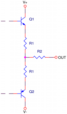
 The circuit at right is an equivalent output stage of an op-amp. Historically, bipolar transistors do better handling current than FETs, so they’re used more than one might expect. For a signal op-amp, the resistors R1 might be in the 100Ω range, and R2 might be in the 50-200Ω range.
Using the TL071 as an example, TI does not actually specify Ro, though they do list values for R1 & R2 as 64Ω & 128Ω respectively. Since the output impedance is thought of as constant, if only one transistor is fully on, only one or the R1 resistors is fully conducting, thus the resistance at the extremes of voltage would be 192Ω. If this were not a constant across all output voltages, the gain of the amplifier would change depending on amplitude. That said, it is an approximation and really serves to draw a line in the sand: don’t expect more than this much from the amplifier.
The same pore-over of a Microchip MCP6441 reveals a different philosophy towards conveying information. No equivalent circuit is given, and no output impedance is listed. This is the place to dig in one’s heels.
It’s an oversimplification, but the easiest way of looking at the problem is to hunt down the relationship of short-circuit current to supply voltage. Looking at Microchip’s graph, there is a huge temperature dependence, so take 25°C as a reasonable starting point. Once the amplifier current limits, the relationship of current to voltage becomes linear, like a resistor. In this case, it works out to Ro = 250Ω. Under Applications in the datasheet, the list of possibilities does not include anything delivering power. This part is made for low-frequency, low-power applications; in these cases the 250Ω is really not a problem.
The temperature sensor amplifier configured in part 1 would be a perfect application for the MCP6441. If feeding the output to the in-built ADC of a microcontroller, say something from Microchip’s PIC18 family, the datasheet warns against connecting anything to the ADC with less than 1000Ω source impedance. This has do do with charging up the input sample/hold circuit; more importantly, we know the source impedance to be 250Ω, so life is good.
How Much Power?
In the above examples, the amplifiers would not be used for directly driving things like speakers. To get a sense of how much can be expected, the concept of maximum power transfer is a good guide. It’s a straight-forward math problem to determine that the maximum power transfer from source to load occurs when the load impedance equals the source impedance. This is why knowing the source impedance is important. If the load has lower impedance than the source, more of the signal energy will be consumed in the source; it’s very inefficient.
The most that can be achieved is delivering 50% of the available power to the load; the remaining 50% is dissipated in the amplifier itself. If it’s a perfect amplifier with 0Ω source impedance, a 0Ω load accomplishes this, right? Ideally yes, but as we already saw…no.
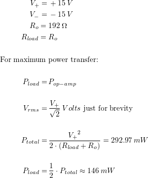
Using a TL071 as an example (and assuming a sinusoidal input), working out how much power it can deliver takes a little arithmetic:
A surface-mount SOIC8 package will not handle this with grace, probably growing warmer until something unpleasant happens. The TL071 has output short-circuit protection, however that depends on either some form of temperature limiting or source impedance from the power supply. In the event the device is driving too low an impedance, the protection built into the device may not save the day; but, this is largely irrelevant. The device won’t amplify properly if its internal short-circuit protection is active, so keeping the part in a safe operating area is still important.
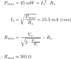
The dissipation limit of a TL071 is an ambient-temperature-dependent parameter, and is shown on a graph in its datasheet. At room-temperature, maximum dissipation is around 45mW; this is very low. Knowing the source impedance, the maximum current that can be supplied at this temperature is just over 15mA.
The minimum load a TL071 can handle in an SOIC8 package at room-temperature is 501Ω. Any lower resistance, combined with a maximum amplitude output, will result in the amplifier current limiting and adding distortion. Though the TL071 offers current limiting, if there is no additional protection limiting the supply voltage or reducing it due to high temperature, you may notice a hiss and/or crackle, and a rather unpleasant aroma; far more entertaining, and possibly a better lesson!
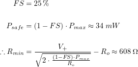
Pressing on with best design practices, it’s wise to have a 25% margin in terms of heat dissipation; call it a factor-of-safety. Redoing the above calculation with reduced maximum power:
In short, just to be on the safe side, do not attempt to drive a load less than 608Ω.
On the other hand, if the supplies are ±5VDC, the amplifier can deliver much less power, but we can get right to the theoretical maximum:
75Ω is much lower than maximum power transfer requires, resulting in a warm-ish amplifier and not much energy reaching the load. In this case, consider the minimum of 192Ω the lowest possible load, and don’t sweat the factor of safety.
Note that the maximum power dissipation is per device; the amplifier IC may have two or four devices. This is not stated, but the graph in TI’s data-sheet makes this fairly obvious by using different curves for their two and four amplifier offerings. They don’t actually say it though, so be careful!
Up next, gain (hint: G < ∞).


Hello Friend.
I’m wondering if I could use a tl071 as preamp to plug a guitar direct to a computer mic in port. sinc my pc does not have line in port. The guitar signal is too low even setting volume knobs and mic volume to maximum. I dont know about impadance issues between mic in and tl071 output
thanks
celso
You might do better with a simple transistor biased into its linear region if you must use a microphone input. On the other hand, if you use a TL071, keep the loop gain low -like under 5:1- use capacitors to isolate the pick-ups from the amplifier circuit, and do the same for the amplifier’s output connection to the microphone port, you should do OK.
The TL071 has a gain bandwidth product of 2.5MHz. If the gain is 5:1 the op-amp’s output should be fairly linear for guitar frequencies. The supply range is 6-30V, so you’ll need either a couple of lithium cells in series, or a 9V alkaline battery; or some other low-noise source of power. Batteries are nice because they don’t add much noise to the amplifier circuit.