In the introductory post, a simple example was presented showing how an op-amp can be used to map a sensitive low-amplitude signal into the range expected by an ADC. Here we look at the difference between idealized and real inputs.
The Allure of ‘Ideal’
On first encountering an op-amp, it looks like a panacea: ∞ input impedance, 0 Ω output impedance; zero offset voltage; flat frequency response from 0 to ∞; ∞ gain; 0° phase shift from input to output; ∞ slew rate, zero noise density, 100% common-mode noise rejection; 100% power-supply noise rejection. So easy to design with…what could go wrong?
Usually it’s shortly after learning of the amplifier’s mythical properties, around the first attempt at building a circuit with one, that non-ideal characteristics burst the designer’s bubble; sometimes with spectacular flare and gleeful entertainment for one’s colleagues. Co-workers: always ready with the schadenfreude when things go wrong. A little ribbing over one’s learning experiences is a right of passage to becoming an expert.
Many ideal properties are listed above; this post addresses primarily the first of them, with brief mentions of offset voltage and noise.
Input Impedance
It is not infinite! This means that yes, some current will flow in to, or out of, the inputs. This means there may be an error in the expected gain of the circuit. The error introduced by current flowing into the amplifier’s inputs is usually negligible however, so it’s the least of all worries. As an example, consider a TL071. As input impedance goes, these are very close to ideal; their inputs are the gates of JFET transistors: Ri = 1012Ω! This is, for all intents, infinite; it isn’t unusual for an op-amp to have input impedance this high. A Microchip MCP6641 has an input bias current of ±1pA, at room temperature. At its temperature limit, this number can be as high as 400pA, so there is a little variance. This won’t come into play in the typical inverting amplifier configuration, unless the feedback resistors are chosen in the high MΩ range.
 A good question at this point is, to what is this impedance connected? Is it a path to ground, supply voltage, non-inverting terminal, or amplifier output? Input impedances are usually specified both as differential and common mode. The differential impedance is between the inverting and non-inverting terminals. The common mode impedance is from each input to ground. To see why this is so, we need to look inside the op-amp.
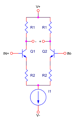
The figure at right shows the equivalent circuit of an old-school op-amp constructed with bipolar transistors. The inputs are actually the bases of the transistors, and being an integrated circuit, their respective β (or hFE) are very closely matched; as are the two resistors labelled R1; same for those labelled R2. This is why the impedance connected to each input should approximately match: a mismatch will cause more current to flow through one transistor than the other, giving rise to a voltage offset.
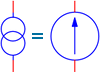 It’s a current-source; equivalent to the more widely recognized circle with an arrow inside showing direction of flow.
TI, ST Micro, and many others usually publish equivalent circuits in their datasheets, however not all manufacturers do. In practice, the inputs are now more commonly the gates of either JFETs or MOSFETs. In the FET case the transistor gates allow very little DC to flow, but the AC impedance will still be affected by a mismatch.
Who cares? Isn’t this a distinction without a difference? These things are so close to ideal that it really matters not; it doesn’t matter until your circuit misbehaves. As a general rule, the impedance seen looking out of the two input pins should match. This keeps the bias currents matched, and minimizes offset voltage. Note also that bias current is not leakage current: one is required, the other grudgingly tolerated.
Leakage current into a FET based amplifier may be in the pico-ampere range, but leakage across the fibreglass or resin of a circuit board can exceed this bias current, and will not help in achieving that perfect match to what the simulator claims. To avoid the complication of leakage currents creating unaccountable offset voltages, guard-rings can be placed around the inputs to the amplifier. These are rings around the pins of interest, connected ideally to the same potential as the input so that leakage current will not flow.
Shrinking component packages make this a lot more difficult to implement; it was viable in the days of predominantly through-hole design. Wrapping a guard-ring around the input pins of an op-amp offered in a DFN package with a ground pad under it is not something the designers of yore ever contemplated; whereas they dealt predominantly with DIP packages of 0.100″ lead pitch, we must deal with leadless DFN packages of 0.020″ pitch.
Swamp it out! A hack yes, but there are not a lot of other options. Ideally, the impedance connected to the inverting input will match that connected to the non-inverting input. If that impedance were several orders of magnitude lower than the 1013Ω input impedance of say, the MCP6441 amplifier, these leakage effects could be ignored.
This matters because in the current quest for low-power, there is a tendency for designers to specify the highest possible impedances; the price of low-power is increased offset error, and possibly weird op-amp behaviour.
Noise
Noise is inescapable and can’t be ignored in an amplifier discussion. There are a large number of sources including RF noise picked up by high-impedance inputs, coupling from neighbouring amplifiers, oscillators or other circuits, even the resistors used in configuring the amplifier.
The inputs of an op-amp are where most noise will be picked up, and yes it will be amplified right along with the desired signal. In audio systems it’s a nuisance, but in instrumentation amplifiers it’s a source of error; some, but not all, can be filtered out.
Up next, real output impedance (hint: Ro > 0Ω).