So far we’ve covered input impedance, output impedance, offset voltage, and talked a little noise; so what’s left? It gets more interesting as complexity increases; this time around it’s about gain, and a first look at using feedback to close the control loop.
This is one of those weird areas of where explaining one thing requires explaining several others; they all must be understood collectively.
Open Loop Gain
So what is meant by loop? If it’s open, can it be closed? Yup. In most amplifier circuits there is an impedance connected from the output to the inverting input; it’s used to reduce over-all gain. This is a negative (stable) feedback loop…closed-loop. If there’s no connection…open-loop. To diverge briefly, there are configurations where a positive (unstable) feedback loop is made, and others called multiple-feedback where the output has a path to both inverting and non-inverting inputs.
We’ll stick to the simplest case for now. Open-loop gain (i.e. no feedback connection) means the amount of gain applied to the difference in voltage between the non-inverting and inverting terminals of the amplifier, appearing at the output terminal.
Typically a small-signal amplifier will have an open-loop gain of 100 to 140 dB. This is quite high; although it can be thought of as infinite, be weary of excessive gain. Open Loop Gain is sometimes called by other names. In TI’s case, they seem to like calling it Large-Signal-Differential-Voltage-Amplification (Avs); for a TL071, it’s 200 V/mV. Hey wait a minute, you ask, isn’t this parameter supposed to be unitless? Yes. It’s a gain factor. Since it’s specified in V/mV, multiply it by 1,000 to make it unitless: Avs= 200,000 (!) or roughly 106dB, right where it was expected. This can be thought of as infinite, but there is a gremlin waiting to pull the rug out from under you…
Gain Bandwidth Product
Time for a reality check. That 106 dB of gain discussed above is fantastic but there’s a problem. This is the source of not-so-flat gain across the amplifier’s limited frequency of operation, and is also a potential source of some troublesome oscillations. They’re nasty, and can kill your amplifier with much less flare than exceeding the thermal dissipation limit of the device.
Gain Bandwidth Product, or GBP, is the product of open-loop gain and frequency being amplified. In an op-amp it is not a constant for all frequencies, but is a constant over much of the range specified by the manufacturer. The higher the gain, the lower the maximum frequency the op-amp can amplify without bumping into its own open-loop gain limit.
Below is a plot showing the gain performance of a Microchip MCP6441 op-amp (Figure 2-15 of the datasheet). Gain is exceptionally high for frequencies up to 0.01Hz, but somewhere around 0.05Hz, it has visibly begun to diminish. The useful bandwidth, assuming consistent gain over some range of frequency is desired, is the horizontal part of the curve.
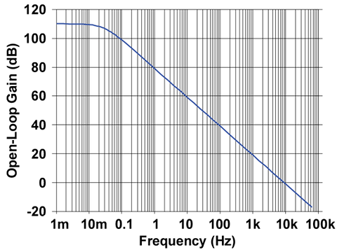
An amplifier that attenuates frequencies above 0.05Hz? What good is that? It depends on the bandwidth of the signal being amplified. Some sensors measure phenomena that change very slowly; ambient light or temperature over the course of a 24 hour period would be good examples. There are very few signals (none?) that require 100dB or more of amplification and have a bandwidth of less than 0.01Hz; using an amplifier in an open-loop configuration is impractical.
Closed Loop Gain
If a signal path is made between the output and the inverting input terminal of the op-amp, this is called negative feedback, or closed loop. Perhaps the easiest to understand version of this is a non-inverting configuration:
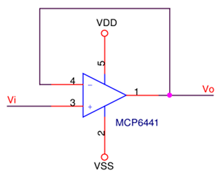 So what does this do? The output is fed back to the inverting terminal, and the amplifier will apply a lot of gain to the difference between pins 3 & 4. If the voltage at pin 3 is 0V, what’s the voltage at pin 1? If the voltage at pin 4 happens to be greater than that at pin 3, the difference between pins 3 & 4 will be negative, but the amplifier will amplify this to a large negative voltage, pushing pin 4’s voltage below pin 3’s, but then the difference between the two pins is positive, so the voltage at pin 1 will be positive and greater than the voltage at pin 3, pushing pin 4’s voltage up and creating a negative difference. It should be pretty obvious that the amplifier’s output voltage will converge on the voltage at pin 3. Extending this, whatever voltage appears on Vi will appear on Vo. So now we have no gain at all! Vo = Vi, and gain is 1:1, or 0dB. It’s called a unity gain buffer.
On first glance, it looks not that useful. If the voltage connected to Vi is a sensor with high impedance of its own, it cannot drive anything, but the unity gain buffer’s output can, as Vo has the same voltage but low source impedance. This is a little pedestrian, and the greater point is, gain is reduced to 0dB; that curve above showing the gain rolling off at 20dB/decade is no longer the amplifier’s behaviour. Draw a straight line at 0dB on the curve, and it looks like the amplifier will dutifully reproduce whatever appears at pin 3 on pin 1, so long as the frequency is below about 9KHz; page 1 of the datasheet for this part shows GBP for this amplifier is in fact, 9KHz. Below is the same plot as above, but with the unity gain curve added. With the closed loop connection, the amplifier will follow the red line.
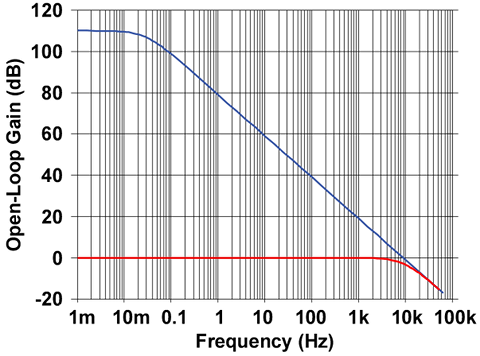
So a little better performance in terms of amplifying frequencies, but other than reproducing a potentially sensitive signal with the authority to drive an ADC input or another amplifier stage, it isn’t doing much. Adjusting the gain between 0dB and 110dB, trades frequency for gain; more gain is seen as the red curve sliding up the vertical axis, but bounded by the blue curve at all times: more gain = lower frequency limit.
Next time around: phase, inverting and non inverting feedback configurations.