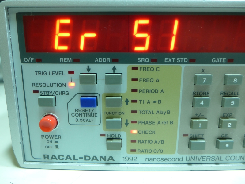
An error message is emanating from our beloved Racal Dana 1992 Frequency Counter. It’s a classic but useful piece of test equipment, and we’d hate to see it go.
Poring over the service manual, the timing error correction hybrid (TEC) is supposed to have a stop count of 800 +/-220; it’s 850 -all good- but the start count is supposed to be half of that +20/-40; it’s 460, should be 385-445. Reading a little further to see if it can be calibrated elsewhere, the troubleshooting chart says “TEC failure,” nothing more. A little casting about online uncovers the rumour that these are made of “unobtanium”.
Turns out, it’s a red herring. The length of the cable is required to be 30-60cm in length, and in this case it’s far too long at 120cm.
As to the display of Error 54 followed by Error 51, this seems related to RLE, an SPDT relay with a 5V, 500Ω coil.
View from the Top.

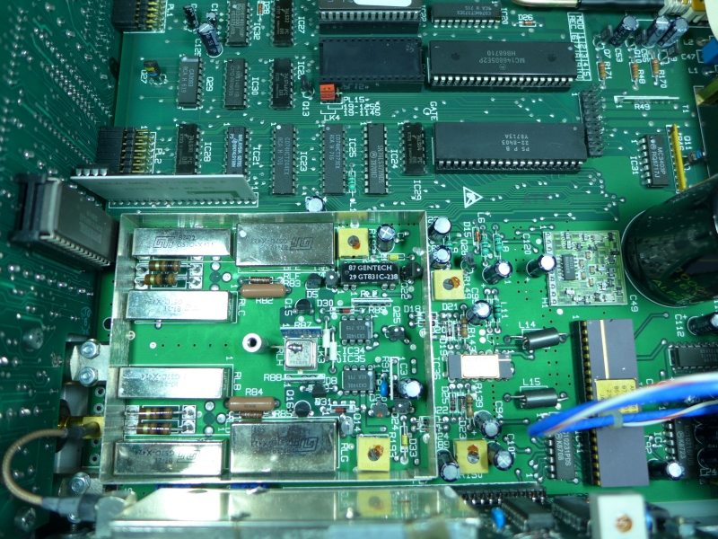
A Closer View
The relay in question is inside the metal barrier, in the upper right corner, labelled Gentech.
The 500Ω coil is a problem. It’s being driven by a 74LS373, which cannot sink more than 20mA per pin, and all equivalent DIP relays have a 200Ω coil. In this equipment, all logic operates from 5V; 5V/200Ω = 25mA, so the ‘LS373 will run out of spec, and certainly fail. A DIP SPDT 1-form-C reed relay with 500Ω coil is a mythical beast at this point. Possible solutions are:
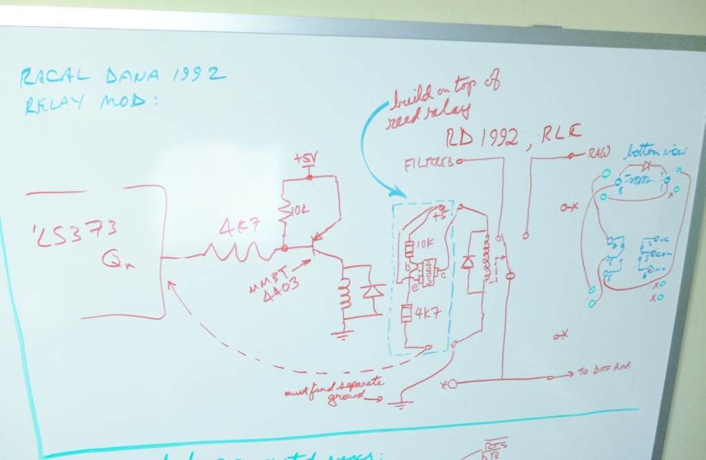
Brainstorming a solution (workable, but messy)
1. Use a modern dip relay with 200Ω coil, but lift the coil leads up, and put an open-collector PNP transistor on it so the LS373 can just sink the transistor base current. This is messy, and will have jumper wires on the board, plus a forest of parts glued onto the relay; but, it will have the signal path going through the reed relay pins on the pcb, as originally designed.
2. Use a telecom relay with a 500Ω coil, flip it upside down and hand wire it into the RLE site. This option is more attractive as it involves less fiddly soldering and a more easily replaced item; not to mention reed relays suck anyway, they’re notoriously cheap and failure prone.
A brief digression… since the relay controls switching in/out the filter for low-frequency noisy signals, and I’ve never used it, I removed the relay, hard-wired the non-filtered path and reassembled the unit. I ran the counter hooked up to a Rubidium reference over-night, and tuned the counter to +/-0.02Hz. The manual says the temperature must be 23°C +/-2°C; it’s 23°C, so conditions are just about perfect. So, though not calibrated with a traceable certificate, I trust it.
Back to the issue at hand, snooping around reveals a nice little telco relay available from Digi-Key, DPDT 2-Form-C _and_ in its uber-sensitive coil flavour, a 500Ω coil!
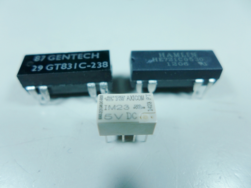
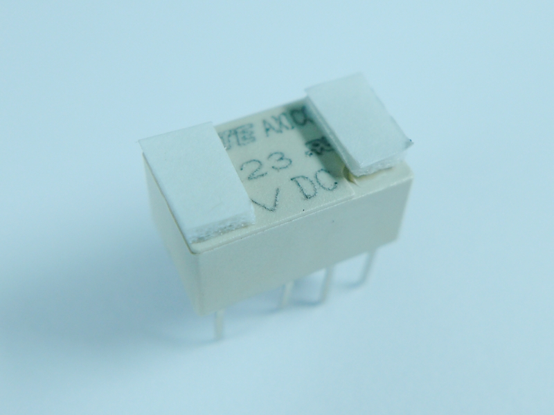
Relays, Old and New.
From left to right, the original relay, the telco (non-reed) relay, and a modern equivalent of the original, unusable due to its 200Ω coil.
A little double-sided foam tape creates a dead-bug style of mount.
One more thing: the telco relay does not include an anti-kick-back diode, but the original reed relay does. This needs to be added prior to installation. Here’s a shot of the mod in progress:
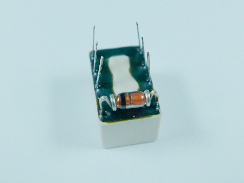
1N4001 diode in a MELF package across the coil.
The diode across the coil prevents inductive spikes from wrecking the driving circuit.
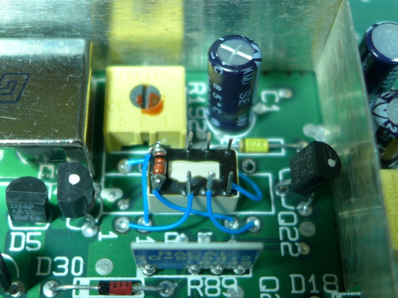
Mounted.
Here it is mounted in place. I think the next time this happens (next time?) I’ll rotate the relay 90° counter-clockwise; it would have made the wiring a little cleaner. In any case there you have it: one telco relay, capable of handling much higher current, same coil resistance as the original reed relay, able to be driven by old-school TTL logic devices like the 74LS373.
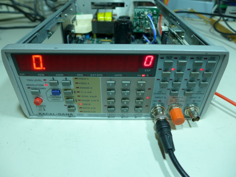
Fixed, passing self-test.
Most importantly, it works! Above, it’s showing the correct display during a test with the 10MHz reference connected to the counter A input. The frequency counter is back in operation; after testing with a function generator, I can see that the filter is being properly switched in and out of the circuit.