Figure 1. 8-element 585MHz Yagi Antenna.
This post comes under the Sidetracks category because it isn’t strictly part of J-Tech’s business (we don’t sell antennas) but it is related to wireless design. There were two objectives to this exercise: 1) learn about the Yagi/Uda antenna from a practical standpoint; 2) get something for nothing.
The “something” in this case, is Television over-the-air (OTA). Learning about an antenna without wanting to either receive or transmit something is a little pointless; why spend the time? I can either pay for a cable or satellite connection (boring), or put up an antenna and see what’s in the air.
Figure 1 at right is a Yagi antenna, the theory and construction of which is the point of this post. The curious reader can find details galore on the origin of this antenna on wikipedia’s Yagi/Uda page; there’s no value in rehashing their information here. These antennae are ubiquitous, with varying numbers of elements, myriad sizes, elaborate reflectors, but what’s so special about them? Simply put, they concentrate signal energy, for both transmitting and receiving RF. Yagi antennae are very sensitive in one direction at the expense of all others. This can have a huge advantage in pulling in signals from a great distance away. The more cross pieces (parasitic elements) on the antenna’s boom, the more directional the antenna. The longer and more spread-out the elements the lower the receive/transmit frequency; the corollary, smaller more closely spaced elements indicate a higher design frequency, is also true.
There are a great many resources available for free to assist in the sizing and construction of Yagi antennae; several were used, and I will make mention of them throughout.
Digital vs. Analogue Antennas
Don’t sweat having a “digital” antenna as is routinely advertised; radio waves aren’t magically different because the information they carry is digital instead of analogue. What’s needed to make all this work is simply an antenna designed to be sensitive to the right frequency.
NTSC, ATSC, QAM256
In the recent past, broadcast television in North America was in a standard format referred to as NTSC, short for National Television Systems Committee. This format has now been officially abandoned in OTA transmissions. Some smaller more isolated communities are still using it, but its days are numbered.
Broadcast television signals today are in a format called ATSC, short for the rather unromantic Advanced Television Systems Committee. Engineers charged with creating acronyms are not poets, apparently. ATSC is more complex than NTSC; for more information, check out wikipedia’s ATSC page. Their info is a little thin on detail, but there are plenty of reference documents listed at the end of their entry.
ATSC is receivable directly by most, if not all, modern television sets. Actually, any television in production today with a screen size of 20″ and up must have an in-built ATSC tuner. It is a legal requirement in the USA, presumably Canada too. As of this writing, ATSC broadcasts are unencrypted; they can be received without special decoding equipment.
Being in a digital format means the quality of the signal is more of a go/no-go affair. If there are no bit-errors in the received signal, the reproduction of the broadcast is perfect; however, if there are bit errors, it only takes a few to render a broadcast unwatchable.
QAM256 is another format for digital television, also receivable by modern television sets but is usually only seen over cable systems, not OTA transmission.
Real vs. Virtual Channel Numbers
There’s an additional wrinkle in understanding how channel numbers relate to broadcast frequency. Historically, to do with the NTSC (the committee, not the broadcast format), channels had pre-assigned numbers: channel X broadcasts at NNN MHz. In ATSC, channels still use the NTSC numbers, frequencies and bandwidths; however, each ATSC signal includes in its own broadcast data, a block of metadata in a format called Program and System Information Protocol, or PSIP. In this metadata is a virtual channel number, allowing the ATSC channel to assign its own number independent of the NTSC number. What the channel says it is, no longer corresponds to its broadcast frequency. The broadcast frequency is the critical thing, as the antenna does not receive at the virtual frequency unless the channel’s real and virtual channels match, or another transmitter is operating at that frequency.
Since the ATSC signal carries digital data, it is possible to squeeze more than one channel into the data of one transmission; hence the need for the virtual channel numbers: it’s possible to have more than one in a single broadcast. This is the case with at least two of the channels I receive. It comes at a price though. A full 1080i HD broadcast needs all of the available bandwidth, so if more than one is squeezed in, data from the primary channel must be tossed out to make room for the additional channel. Usually what I see is one HD channel and an additional one or two SD channels lurking in the signal.
Bands – VHF, FM, UHF
One drawback of most antennas (including Yagis) is that they’re tuned for one frequency, but it’s desirable to receive a range of frequencies. A channel is broadcast on a frequency, just like a radio station. If an antenna is perfectly tuned to one channel in the TV band, it is not tuned to any others; however, it will still pick up other channels not at that perfectly tuned sweet-spot, just not as well. In this case the antenna is said to be mis-matched. This is OK too, as most antennas do well with signals of lower frequency than their design, but tend to fall off sharply at higher-frequencies. Obvious solution: design for a frequency toward the top of the UHF band; channels above the design frequency will be few, channels below will be many, and the antenna will do reasonably well for most. See Elements below for a few words about how component selection can affect bandwidth.
Before sweating the details of the antenna itself, think about the desired frequency range. VHF and UHF are the two bands carrying all OTA television broadcasts. The VHF band has been largely abandoned in favour of UHF, and the UHF band for TV use has been cropped a little. Each channel gets its own 6MHz bandwidth into which the various components of a television signal are transmitted.
In VHF, the bottom of channel 2 is at 54MHz, the top of channel 6 is at 88MHz. Somewhat weirdly, for historical reasons really, the FM radio band is right above channel 6, 88-108MHz; it’s in the middle of the VHF television band! There’s a big jump in frequency between channels 6 & 7. Channel 7 starts at 174MHz, and channel 13 ends at 216MHz. Above this, starting at around 300MHz, is UHF. Before everybody gets excited about VHF digital broadcasts in their neighbourhoods, if all of your OTA stations broadcast in the VHF band, hey, build an antenna for the VHF band. In my case, there’s nothing there to receive.
Although the UHF band begins at 300MHz, television channels are between 470MHz and 890MHz, much higher than the VHF band. That’s a big range, and it’s a tall order to make an antenna do well for the whole span; however, there may not be anything broadcasting in a lot of it, so the requirements of the antenna can be simplified.
All or Part of the UHF Band?
So, what is there to be received? Wouldn’t it be nice if there existed a service where you could punch in your longitude & latitude and a map could show you what transmitters are operating in your area? Answering my own contrived rhetorical question, yes, there is such a service: TV Fool. Don’t know your longitude & latitude? No problem. Use Google Earth to figure it out, or just punch your home postal code, or zip code. Addresses are not that precise, so coordinates will give the best data possible. In my case, the output looks like this:

Figure 2. ATSC Transmitters Operating Near-by, data as shown at www.tvfool.com
In the circular region above, the antenna will sit at the bulls-eye, and anything in the green space can be reliably received. Looking at the lower right UHF chart, anything below about -50dBm will be reliable only some of the time. Transmitters outside this region are more difficult to pull in consistently. They can be had with some effort, but I’m a dilettante in this realm; I just want the low fruit. More seriously, transmitters in the green rings are likely to be available year-round in all weather conditions with a minimum of fuss; by minimum, read: none. Part of my issue is there are other buildings, hills and trees in the way, so while the chart may show -50dBm, and some will say this should be easy to get, it is not so.
The channel map is a bit of a mess; most of the easy-to-access stuff is at 337°, roughly 11 o’clock, but there are a few goodies available at 157°, roughly 5 o’clock. Note the four channels not on that 337°/157° axis. Channels 23 and 39 are repeaters of channel 22 at 337°, so I’ve already got those. Channel 47 is one of the weakest signals at -94dBm, and does not carry content of interest. Channel 49 is in reach, but also does not carry content of interest, so if it just happens to come in, great; if not, I can live without it. Note also there’s only one VHF channel, far outside of the green rings. Cutting away all that chaff leaves viable channels at 180° apart. Getting signals from two different markets as they’re called, is tricky. Either the antenna must be rotated, or two antennas must be used, or a sacrifice must be made. To keep this simple, I’ll limit the effort to the 11 o’clock direction. In my neighbourhood, this is an array of transmitters on Mt. Seymour.
Focusing on the table in the upper right corner of Figure 2, specifically the column marked “Real”, and sorting the channels numerically, the desirable range of reception is from channel 17 at the bottom to 43 at the top: from 488MHz to 650MHz. The station with the most content is probably channel 32, or CIVT-DT, or between 578MHz and 584MHz. Nicely, and unusually, their real channel matches their virtual channel. Designing a Yagi for somewhere close to 581MHz hits that sweet spot of being in the top half of all of the desired frequencies, so I will likely pick up everything I’m looking for.
Somewhat arbitrarily, 585MHz was the design frequency of choice. There’s is a small scale method to the madness in not centring the antenna right at 581MHz, as one might think obvious. If the antenna sees (is resonant at) one frequency over all others, the receiver to which it’s connected can become overwhelmed by this one signal, a.k.a. swamped. It may have been wiser to centre the antenna at around 610MHz to keep it above channels 32 & 33. Note channel 35 comes from the other direction (basically a rerun station, of little interest). The only channel above this is 43, CBC, 647MHz (ish) which has incredible broadcast power.
Antenna Parts
Common terms used in reference to the antenna:
Boom
The piece to which all elements are fastened. It can be conductive or non-conductive, builder’s choice. The lengths of all elements are different depending on whether the boom is conductive. Since this is a budget antenna, the it will be of non-conductive plastic.
Elements
The conductive bits perpendicular to the boom, consisting of three different types: the driven, the reflector, and the director(s).
The diameter of the elements is important. Larger diameters produce an antenna with a wider bandwidth; for a broadband receiving antenna this is a good thing. It makes the antenna less sensitive to one specific frequency and more able to see a broader range. Choosing bigger diameter material will also mean slightly shorter element lengths; also a good thing, as less overall length of material is required.
Driven
The dipole is the driven element of the antenna. In the case of a transmitting antenna it’s the part connected to the RF amplifier, and is what radiates the RF energy. Since I’m only receiving, the driven element, strictly speaking, is not driven; but it’s still the right term.
It is actually a folded dipole; they take up a little less space and require a fairly easy-to-make balun. More on the balun later.
Reflector
The longest cross piece of the antenna, on the opposite side of (behind) the dipole; basically the back end of the antenna. This piece is sometimes more complex than the simple length of metal discussed here. Occasionally it’s a screen, or a parabolic reflector. Keeping it practical, a single length of metal rod will do nicely.
Director
A parasitic component of the antenna; one of the unconnected cross-pieces between the dipole and the signal being received. Usually there are more than one of these. Opposite of the reflector, these elements are more capacitive, and hence tend to draw the signal (when transmitting).
In RF parlance the director is more capacitive (lower impedance) than the driven element, and the reflector is more inductive (higher impedance). Since the directors present an easier path through which RF energy can flow, when transmitting, more energy flows through/past the directors, and when receiving, more energy comes in through the directors.
Balun
Told ya I’d come back to this. This is short for balanced to unbalanced. What it does is something called an impedance transformation. It matches one load to another. The impedance of the folded dipole is roughly 300Ω, but the receiver is looking for 75Ω, and the coaxial cable I’ll be using has a characteristic impedance of 75Ω. That’s a lot of jargon, but conveniently, and not accidentally, because a 4:1 impedance ratio happens to be required, a simple piece of coaxial cable cut to 1/2 a wavelength at 585MHz can be used to make the balun. The Yagi application shows how to connect the balun to the dipole and the cable.
Mast
The object to which the antenna boom will be fastened. It could be a tree, an amateur radio tower, flag-pole, or anything that will get the antenna off the ground.
How many directors?
The stated purpose of this blog post is to give a method of working out what to design and how to go about it, not to reinvent all of the calculations necessary to developing a Yagi antenna; the actual math is not trivial, and differs depending on the number and shape of the elements, and the shape and material of the boom.
There are some amateur radio operators out there truly in a class of their own. One is John Drew, VK5DJ. I have never met or communicated with Mr. Drew, however he has produced an amazing application for developing Yagi antennae. Before hounding the gentleman, realise he is not a commercial operator, so his application must be treated as not supported. If you get stuck, you’re on your own.
Each additional director focuses the antenna more tightly on its target: the television transmitter. Think of the antenna as sitting at the vertex of a cone, with its boom on the axis. Anything within that cone will be seen by the antenna, but the closer the transmitter to the axis of the cone, the better the antenna will be able to see it; much like your eyes see objects directly in front, but not so clearly in the periphery. How wide is the cone? Is it it super wide like a limpet, or super narrow like the sharpened tip of a pencil? The term for this is beam-width, and it’s influenced by the number of directors. Fewer directors allow the Yagi to see transmitters in a wider angle, however if the broadcast signal has been reflected off buildings or trees, these signals will also be received. Since they have taken a less than direct route to reach the antenna, they will not be in sync (phase) with the signal received directly, and will interfere with reception. The number of elements should be selected to produce a narrow enough beam-width to reject multipath signals, but wide enough to not be excessively difficult to aim.
Using an application allows simple trial-and-error attempts at coming up with a workable design. It also allows the builder to account for details of the materials available. I chose an 8-element Yagi with folded dipole. This gives a 3dB beamwidth of roughly 41°. What does this mean? If an antenna is pointed directly at the transmitter, the transmitter is said to be at 0°. If the antenna is pointed +/-20.5° of straight at the transmitter, the strength of signal received will be cut in half. This makes the antenna reasonably sensitive, able to screen out a lot of interference, but not so sensitive that it requires a laser sight to align it with a transmitter.
Here is the output of VK5DJ’s program:
VK5DJ's YAGI CALCULATOR

Yagi design frequency = 585.00 MHz
Wavelength = 512 mm
Parasitic elements fastened to a non-metallic or separated from boom
Folded dipole mounted same as directors and reflector
Director/reflector diam = 6.35 mm
Radiator diam = 6.35 mm

REFLECTOR
248.1 mm long at boom position = 30 mm  (IT = 109.9 mm)

RADIATOR
Single dipole 237.7 mm tip to tip, spaced 102 mm from reflector at boom posn 132 mm (IT = 104.9 mm)
Folded dipole 242.4 mm tip to tip, spaced 102 mm from reflector at boom posn 132 mm (IT = 106.9 mm)

DIRECTORS
Dir	Length	Spaced	Boom position	IT	Gain	Gain
(no.)	(mm)	(mm)	(mm)		(mm)	(dBd)	(dBi)
1	215.3	38.4	170.9		93.3	4.8	6.9
2	212.5	92.2	263.2		91.8	6.5	8.6
3	209.8	110.2	373.4		90.8	7.8	9.9
4	207.4	128.1	501.5		89.3	8.9	11.0
5	205.1	143.5	645.0		88.3	9.8	11.9
6	203.0	153.7	798.7		87.3	10.5	12.7
7	201.1	161.4	960.1		86.3	11.2	13.3
8	199.3	169.1	1129.2		85.3	11.7	13.9

COMMENTS
The abbreviation "IT" means "Insert To", it is the construction distance
from the element tip to the edge of the boom for through boom mounting

Spacings measured centre to centre from previous element
Tolerance for element lengths is +/- 2 mm

Boom position is the mounting point for each element as measured from the
rear of the boom and includes the 30 mm overhang.The total boom length is
1159 mm including two overhangs of 30 mm

The beam's estimated 3dB beamwidth is 41 deg

A half wave 4:1 balun uses 0.81 velocity factor User defined coax and is
208 mm long plus leads

FOLDED DIPOLE CONSTRUCTION
Measurements are taken from the inside of bends
Folded dipole length measured tip to tip = 242mm
Total rod length =532mm
Centre of rod=266mm
Distance BC=CD=96mm
Distance HI=GF=91mm
Distance HA=GE=130mm
Distance HB=GD=170mm
Distance HC=GC=266mm
Gap at HG=10mm
Bend diameter BI=DF=50mm

If the folded dipole is considered as a flat plane (see ARRL Antenna Handbook)
then its resonant frequency is less than the flat plane algorithm's range of 10:1
About the Results
First, a caution: since Yagi antenna modelling has developed by text-book use of scientific method – build antenna (hypothesis), measure performance (test), use results to develop equations to fit observations, and repeat – it should be noted that different models apply in different situations. It is acknowledged in several places that the program is intended for “long” Yagi antenna designs, in which the boom is at least two wavelengths of the design frequency, requiring 10 or more elements. At 585MHz, one wavelength is 512mm, and the boom is 1099mm from reflector to front-most director, so this is a good choice.
Second, a tip: the boom length given assumes it’s long enough to hold all elements including dipole and reflector with 30mm of overhang at the front and back. Unless the intent is to mount this by clamping it between two of its elements, allow an extra 150-250mm behind the reflector. A clamp for mounting the antenna can be put there.
Material Selection
For the boom, I opted for a piece of PVC electrical conduit. It’s light, reasonably rigid given only ~116cm is needed for the whole antenna, and non-conductive.
For the elements, dipole and reflector, I used 1/4″ or 6.35mm diameter copper tubing. It’s very inexpensive, easy to cut, easy(ish) to bend into a folded dipole, and easy to straighten (comes in a coil).
For the balun, and coaxial connection to the receiver, there happens to be a big spool of RG-6 coaxial cable available (left-over from another project). The cheaper variety of cable, RG-59, can also be used, and is easier to bend/coil for the purpose of the balun, but RG-6 works well in terms of signal attenuation, and it’s already at hand.
To hold the balun and dipole and coaxial cable together, a non-conductive box of some kind is needed. A small ABS or similar project box will do nicely.
Cutting & Drilling the Boom
If you want it neat, a chop-saw is a good choice. If it’s less important, any hand tool will work, it’s just PVC. It could even be cut with a knife.
Since PVC conduit is only required to be approximately straight, don’t count on it being free of bends. It comes in 3m/10′ lengths and only a small portion is required, so pick the straightest section possible. Lay the tube on a flat surface and look down its length. There will be an arc, possibly a spiral (avoid buying if it has a helical twist). In the short length required it shouldn’t be catastrophic, but since it will have elements fastened to it and a clamp at one end, some droop is unavoidable. Use the bend to your advantage. Drill all of the element holes perpendicular to the arc, and when mounting the antenna, the arc of the boom should be oriented upward. Gravity will straighten it out, and you may end up with no droop at all.
Drilling the holes for mounting each element is almost as difficult as folding the dipole (see below), maybe more so. Measuring the distance between each element is easy, but there’s no flat surface anywhere on the tube! Each hole must not only be exactly the right distance from its neighbouring elements, the drill bit must pass through the axis of the boom, must be perpendicular to the boom, and must not have any radial rotation; it’s a tall order if clamping in a vise while hand drilling.
This is probably easy to accomplish in a machine shop, but a garage is unlikely to have a drill press with a big XY table. A drill-press with a vise is a big help, but will not eliminate the possibility of the boom rotating between drillings. A useful trick is to fasten the boom to a 1×2 piece of wood or other rectangular object. This will help keep it from rotating. Two attempts were made to get this right, but at less than a dollar per metre, it’s more of a time-spent than a cost issue.
Fabricating Elements
To cut the elements, a hack-saw works but requires pinching the copper pipe in a vise, so is not a great choice. If a pipe-cutter or a dremel drill with cutting wheel attachment is available, this works better. This process takes some time. The procedure here was to cut intentionally long by 1-2mm and grind the elements to the right length afterwards.
Inserting the Elements
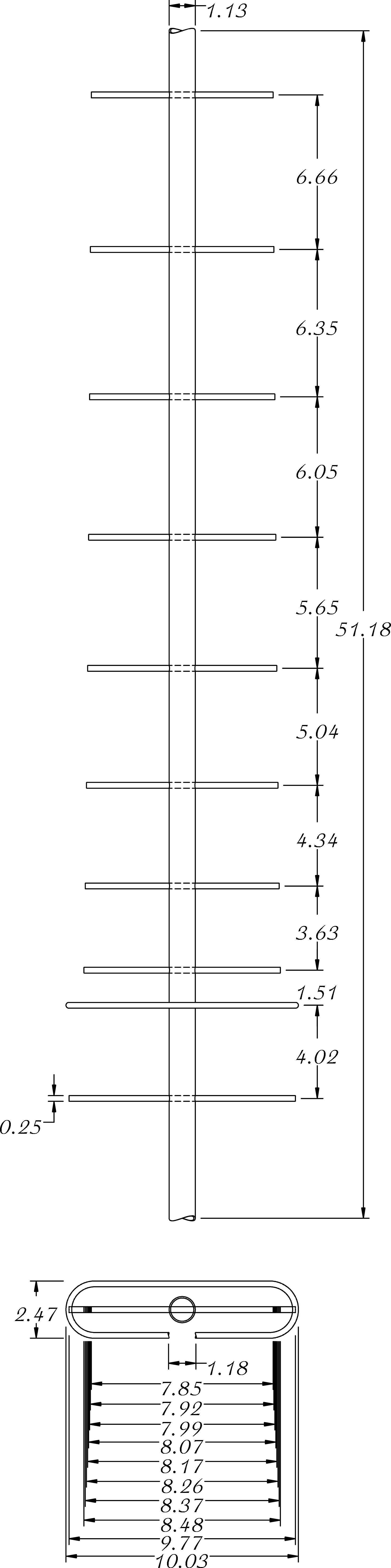
This is where you discover how good you are as an amateur machinist. Inserting the elements is easy enough, but the final product should have all elements exactly parallel, 0° rotation angle from one element to the next, and coplanar. See below for an illustration:
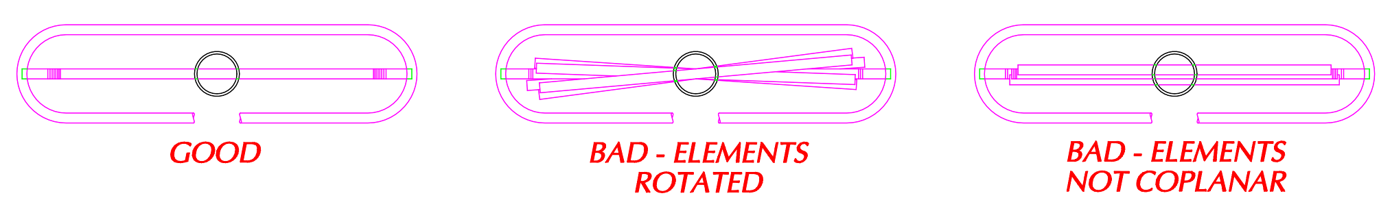
Figure 3. Front View of Yagi Showing Exaggerated Illustration of Boom Drilling Errors.
If it’s not perfect, don’t panic; the elements can be bent a little (within reason) to help line things up. It’s just soft copper after all, and this antenna is not high-precision military technology. The closer the tolerances the better the end result, and the less fiddling needed.
Dipole
Possibly the most difficult part of the job. Bending 1/4″ copper tubing to the correct length is helped immensely by a pipe-bender, not commonly found in a toolbox. If you know a plumber, this is a good time to trade libation for tool rental. If a vise is available, a rope pulley can be used as a guide too, but it is still a challenge, as the tubing will want to crease as you bend. The hand-held pipe bending tool I used couldn’t bend radii less than 25mm, which makes the diameter of the bend 50mm.
If the ends aren’t bent to the correct length, the material is soft enough that small adjustments can be made by straightening one side, and bending the other. Copper will work-harden the more it is bent and straightened, so it gets a little tougher to work after each adjustment. Much patience was required to get this right. It’s easier to cut the dipole piece longer than required, bend it to the correct diameter and span, then trim the ends to centre the gap.
The choice of material mentioned above will bite you if you get too aggressive. The tooling required for bending the dipole will have a cost proportional to the diameter of material selected: bigger tubing means more sophisticated tools.
The cable and balun must be attached to the dipole at some point. The ends come into the plastic box, and I drilled small holes through them so as to insert the centre-wires of the coax cables. One side can have two holes: one for the balun, one for the receiver connection, or the balun can be twisted together with the cable connection. Two holes is a little neater. These can be soldered directly to the dipole, but a robust (high-powered) soldering iron is required; the dipole is a giant heat-sink and will cool the iron’s tip very quickly. A soldering gun works well for this. The more powerful the better because once the dipole is inserted through the walls of the box, heating it will soften if not melt the box. Use a little steel wool to buff the oxide off the dipole tips before inserting into the box, and be ready with flux and solder so the operation can be completed as quickly as possible. See Figure 4 in the next section for the connection points to the folded dipole.
Balun Construction
This is a little tricky. Part of the problem is, although the Yagi Calculator will do it for you, the correct cable must be selected. Selecting RG-6 did not work, as the length depends on the velocity factor of the cable; the cable on hand has a different velocity factor than the application assumes.
What the heck is velocity factor anyway? RF travels at the speed of light, in a vacuum: 300,000KM/s. It’s not so fast inside a piece of coaxial cable. The simple term used to describe the discrepancy is Velocity Factor. Since the signal is travelling slower, it doesn’t cover as much distance over one wavelength. In order to get the required ½ wavelength of cable, one half a wavelength in a vacuum must be multiplied by the velocity factor. At 585MHz, ½ wavelength is 256.4mm. Multiplying this by the velocity factor of 0.81 gives ~207.7mm. This is how long the coaxial cable must be excluding the loose ends. Note that if the velocity factor is known when running the program, a custom cable for the balun can be selected, and the velocity factor simply specified.
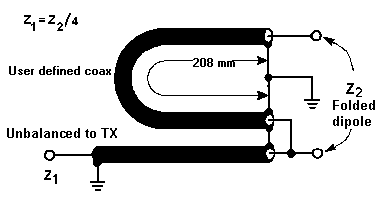
Figure 4. Balun Made with Coaxial RG-6/U Cable with Velocity Factor 0.81, ½ wavelength at 585MHz. Image from VK5DJ’s Yagi Calculator.
Since I don’t want a piece of coax hanging down under the antenna, and this will be outside year-round, a box is a good idea; the balun can live inside, and it should be non-conductive so as to not affect reception. The box with the dipole ends pressed into it was chosen for this purpose. Bringing the folded dipole ends in too means that the balun connections are protected from the elements. The balun piece does not have to be a U shape as shown in Figure 4; it can instead be coiled, but not too tight! Forcing the coax into a tight coil can affect its characteristic impedance, throwing off the impedance transformation. The box I used is smaller than it should be, but not too much smaller. My reasoning is, usually a balun’s purpose is to match a transmitter to the antenna, the source impedance of which should match the characteristic impedance of the transmission line (the coax). If the match is poor, some of the transmitted signal is reflected back into the system, and dissipated as heat; that’s bad. In this case, I’m only receiving, so there’s no chance of damage, but I want to receive as much of the television signal as possible. Since everything’s in the box, the coax connection to the receiver can be made in here too. Call it paranoia, but it occurred to me that the screws used to hold the box together might interfere with reception. I ditched them and used two large zip-ties to simultaneously hold the box shut and fasten it to the boom. It’s probably just silliness as the length of the screws is nowhere near the wavelength being received, and did I mention there’s a coiled up balun and coaxial cable with a ground shield sitting right there anyway?
Dipole location on the boom is critical to reception. Not wanting it to move around, I used a little hot-glue to fix the box supporting the dipole to the boom. I also used a little dab on each element just to keep them from moving. The elements themselves could slide if the fit is loose, and the folded dipole should be in a plane perpendicular to the boom and not able to rotate. Another objective is to keep the dipole centred both vertically and horizontally on the boom axis. In order to pull this off, holes drilled in the plastic balun box must be calculated such that when the box is pressed against the side of the boom, the folded dipole’s widest point should line up perfectly with the rest of the elements. See image at top for an front view of the antenna.
One additional problem: whereas conventional coaxial cable used plated copper for the woven shield in the coaxial cable, newer coaxial cable uses plated Aluminium. Not a big deal, except that it’s not easy (found it impossible actually) to solder the balun and coax shields together. I ended up using a household wiring marrette to hold the shields from the two ends of the balun and the incoming coaxial cable together; not the prettiest solution, but after 30 min of trying to get solder to wet Aluminium, and wrecking several pieces of coax, one looks for alternatives.
Mounting
Once the antenna was finished, how to mount it? Generally the higher up above obstacles the better, so a roof-top mount is a good idea.
For initial testing, I clamped the boom behind the reflector in a bicycle stand. This turned out to be very convenient. The stand allows for rotation up, down, left & right, and for height adjustments. Once it was confirmed working; i.e. getting lots of that sweet sweet free high-definition 1080i television signal, well I couldn’t very well leave a bicycle stand up on the roof, now could I? The probability of needing it to repair a bicycle was, and is, quite high. Then there’s that pesky issue of wind.
To mount the antenna on the roof, a J-bracket for mounting a satellite dish was used. The bracket was (is) fastened to a roof peak, and to the bracket was fastened a 2 metre length of 1.5″ diameter Aluminium pipe. This happened to slip right inside the J-bracket. It was purchased from a metal supermarket, and was much less expensive than expected.
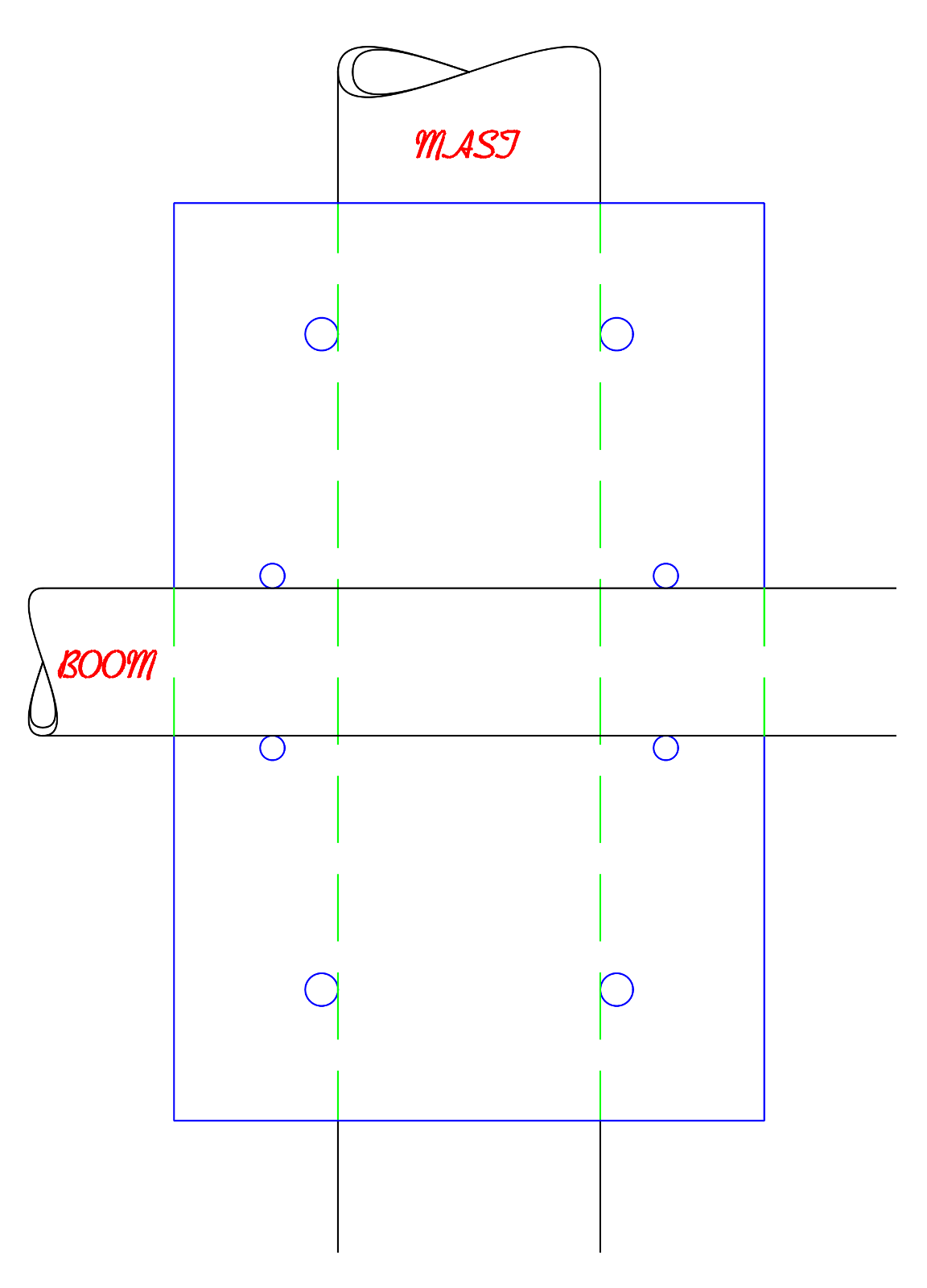
Figure 5. Mounting Plate Showing Mast and Yagi Boom
Mounting to the mast was accomplished by cutting a 3/8″ piece of ABS plate to a 4.5×7″ shape; for the metric minded, roughly 9.53x115x180mm. The plate dimension needn’t be precise. Need four U-clamps: Two in 1.5″ diameter to grip the mast, and two in 1.125″ diameter to grip the
boom. McMaster Carr is a great source for all things U-clamp. Whereas the plate dimensions can be a little loose, the holes drilled for the four U-clamps must be arranged in a cross, and should be exactly 90°. I admit I didn’t work from a drawing for this part, but Figure 5 at right shows what I’m describing.
Vertical vs. Horizontal Elements
Orientation will doubtlessly come up. For television, the elements should be horizontal; for FM radio, vertical. The reason for this is that RF signals are polarized; the angle depends on the orientation of the transmitting antenna. The orientation of the receiving antenna should match the transmitter. FM is mentioned only as an example of a differing orientation; the point is that it’s something to check. The antenna will still work with the orientation wrong, just not as well.
Ground
One last mounting issue is grounding. Putting an antenna on a rooftop and connecting it to a receiver brings the possibility of a lightning strike wiping out the receiving equipment. There’s no escaping that risk, so it’s a necessity to ground at least the coaxial cable to earth. If you follow this blog post, build and install an antenna on your roof, you do so at your risk, not mine! I am not responsible for you not hooking up your antenna safely.
Residences have a rod driven into the ground and clamped to the metal conduit in the building. Usually the rod can be found sticking out of the ground where power enters the building, near the electrical meter. A ground block for coax has two female coaxial connectors, but also includes a screw terminal for grounding the shield on said coax. Use a heavy ground wire here, do not skimp.
Finished Product
A few pictures showing the important bits of the antenna:
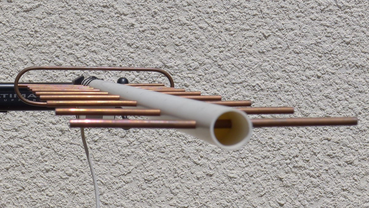
Figure 6. Yagi, Clamped into the Fabled Bicycle Stand, sans Mounting Bracket.
The elements all being copper means they’ll discolour over time. These pictures were taken a little while after construction, and a patina is clearly already forming. This should not affect performance. I thought about plating or coating the copper with something so as to preserve its shine, but other than looking pretty, in itself a debatable point, there is no benefit.
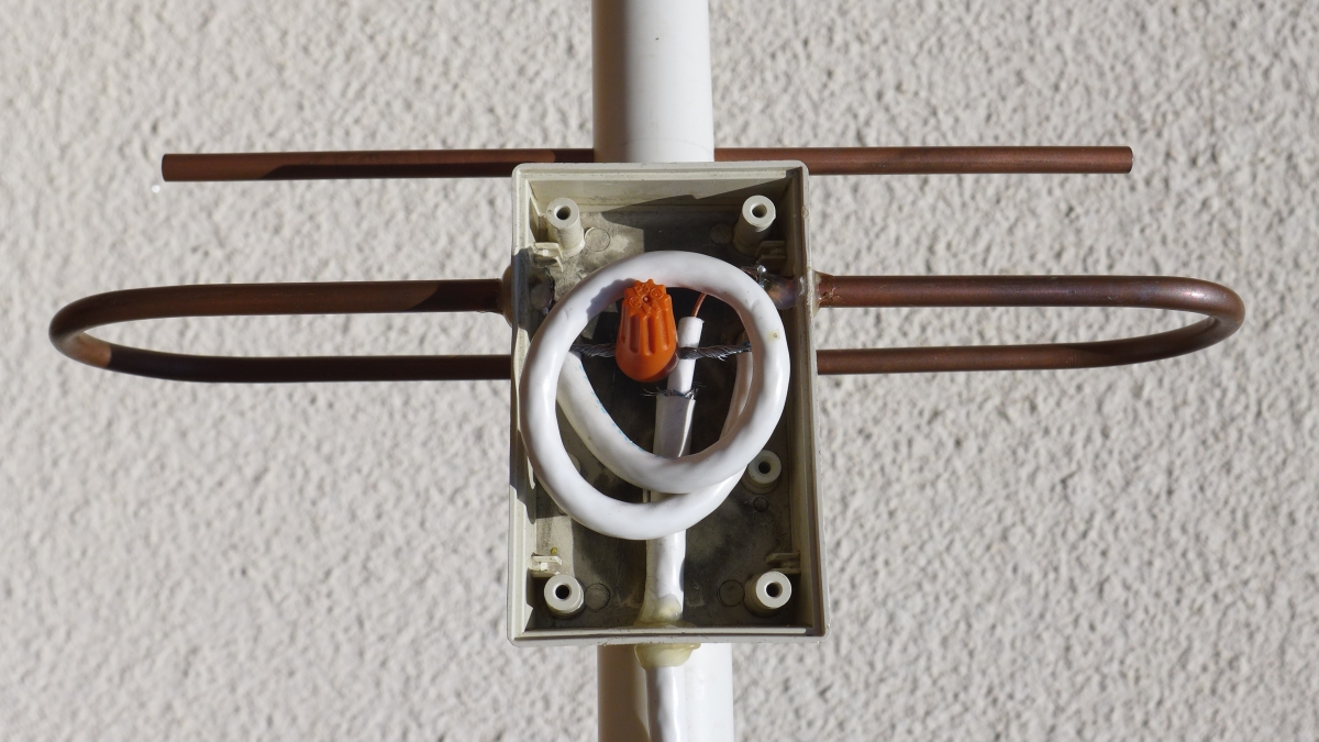
Figure 7. Balun, not Pretty, but it Works.
Note the marrette above. Since the Aluminium ground shields will not wet with solder, the marrette makes an easy alternative, even if it does look a little clunky.
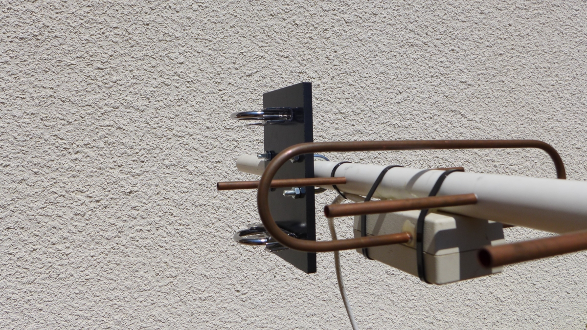
Figure 8. Mounting Bracket, Balun, Folded Dipole, & Reflector.
The mounting bracket is shown above. If I were doing this again, I’d make the bracket a square, and put the U-clamp holes on the biggest diameter circle I could fit on the material.
Got mad skills… what else can I do with this?
It turns out it’s a lot more fun to make a Yagi antenna and write a blog post about it than it is to watch TV; queue Springsteen’s “57 channels (and nothin’ on)!” What else could this be applied to?
Cell service in Canada is generally good, but once you’re off the beaten track, it’s unlikely there will be a cell tower near by. It would sure be nice to extend the range when off-road. Cell phones use much higher frequencies than television, which translates to a much smaller antenna.
The biggest obstacle is the disappearance of antennas on the outside of cell-phones. They’ve migrated inside the device, and there’s no connector anywhere for an external one. Does there need to be? Why not make a Yagi with just the parasitic and reflective elements, but no dipole or balun, cut for cell-phone frequencies. Leave a gap in the boom so the phone could be held in the right spot, hook up a blue-tooth headset and it’s possible to reach a tower from quite a ways further out than normal. I haven’t quite figured out how to leave a gap in the boom, but at glance, four ABS elbows and a little of that left-over conduit might make it easy to both hold the phone in place and fashion a handle. This is much simpler because there are no cables, balun or folded dipole to worry about.
The most obvious thing is wifi. Wifi is mostly in the 2400MHz band, but some standards support 5GHz, which means a smaller antenna than even the cell-phone version. This would require different coax, and SMA connectors, and could really extend the range of wifi for certain devices. Seems like external antenna connectors are disappearing from this environment too; could be smart to do something like the gapped-boom idea, then just slip the side of a tablet into it.
Nice article,plan on making four stack h box array,thanks for your good work,More fun to make,than watch tv.
This is one of the best tutorials about building a yagi antenna i have seen. There are so many out there, but most completely skip how to actually build a balun / match impedance. Also great illustrations for the yagi elements.
Great tutorials on antenna (especially of YAGI’s designs) and OTAs trans/recv basis… really informative, thanks again.
In this example, is the coax cable soldered directly onto the copper pipe from the driven element?
Yes. The centre conductor of the coaxial feed line (RG6 75Ω) is soldered to one side of the driven element. The balun is a ½ λ of the same coax; one end solders to the same place as the feed line, the other end solders to the other end of the driven element.
The coax has copper plated steel for a centre conductor, so it’s quite stiff. I used a dremel tool to drill small holes through the ends of the driven element; two holes at one end, one at the other. I then inserted the centre conductors into each hole so they passed right through and could be soldered on both sides of the copper pipe. This gave it quite a bit of strength.
The shield from both ends of the balun and from the feed line are joined together with a marrette. I would have preferred to solder them together, however the shield on this cable is Aluminium, so it does not take solder.
I’d have thought an old hand like the one making this yagi would know that there’s an easy way to solder aluminium. All you need to do is put some light oil on the aluminium, scrape through that with a knife, and the oil will stop the oxidation just long enough for you to solder to it. Give it a try!
Excellent! Have you done this successfully?
nicest tutorial on building yagi antenna. am working on stacking two identical yag antenna
Did you get them to work as hoped? I’m wondering about stacking 2 myself, or making a cube of four. I’m thinking now of how to sum them successfully.
Kevin in Waterford
I really enjoyed going through your article after stumbling across it hoping to find a better design for a balun for an antenna I’ve “invented”. Being sick of the outrageous cable tv bills started me with antennas and living in “deep fringe” with a broadcast range of 208 degrees left me with few purchase options for an omni-directional antenna. So, I built one using bowtie dipoles and the design works really well. The balun used on the antenna was bought from eBay but I love to DIY and wanted to build one myself. Thanks for the insights. Currently, I am considering adding reflectors behind the dipoles to really pump up the reception.
Regarding your not plating or finishing the copper… This has been a nagging concern for me. I live a little over a mile the ocean and EVERYTHING oxidizes. Do you think dipole oxidation might reduce reception?
Thanks again for a truly insightful and helpful paper.
Glad you liked it, thank-you. With respect to the choice of cable, this is what was to-hand. 75Ω cable is available with copper shield and centre. As to the proximity to the ocean, I’m about the same distance from the Pacific, so it’s a concern here too. I haven’t noticed any problems in the couple of years it’s been in service. I suppose the centre conductor could rust through, but it’s inside the little box, so there’s no water hitting it, and the salt-laden air doesn’t flow through the box much. The copper elements long ago developed a deep brown patina, but it doesn’t seem to affect reception. If they rot out, I’ll cut new ones.
If you need multi-directional reception, you can always use more than one antenna. It gets a little tricky because they can affect each other negatively if connected to the same piece of coax. I used a conventional splitter to join a North-facing to a South-facing antenna. If you know what frequencies are in each direction, you can cheat a little by cutting each antenna for it’s most desired channel. It won’t solve the problem completely, but it will probably let you receive channels from two directions at once.
Another alternative is to have one antenna for each market and bring them each into separate tuners. If you have a PC with multiple tuner cards, you’re in business.
Multi -directional is EASY!! BUY a ROTATOR, when you watch TV, you rotate it toward the city it’s from( assuming you know what towns are around you) to clear up picture and avoid pixelating! SIMPLE! NO compasses, computer algorithms, TVfool junk, longitude/latitude junk! Just like everyone’s been doing since the beginning of TV, 1940-to-TODAY!! Some of today’s children STILL THINK that world was invented in 2000.
Terrific explanation of the balun! I never really totally understood it’s function until you explained it. I am building an antenna to use in Port Moody and am wondering how much gain I need to design for. During the 2010 Olympics I was able to watch it on digital tv on rabbit ears, no problem. During the last two days I have been trying to get reception onto two tuners (redundancy for tests) with various high gain antennas, including a LPDA, old school TV antenna UHF/VHF promising 100 miles of reception from transmitter, etc. I double checked all cables for continuity, was careful about impedance, etc. No go. I am basically at sea level in Port Moody on the 2300 block on Clarke Street, about a kilometre and a half from Rocky Point. I pointed antennas to Mt Seymour. With another tool I could measure signal where channel 22 is supposed to be. But no luck with picture. I wonder if the new sky train and other development has brought into play new RF that is desensitizing my receiver? So, perhaps I have a problem with signal strength from the TV broadcasters as well as “splatter” from other unknown RF transmitters?
Thanks!
You’re really close to Mt. Seymour (under 11km). I would expect an easy time picking up stations, unless there’s a mountain or buildings between you and the transmitters. CBC (channel 43, ~644MHz) should come in at above -30dBm, which is really strong (signal strength here shows max’d out even when split between two TVs and you should have over 6x more signal at your location).
I don’t think skytrain would cause interference, as they don’t -to the best of my knowledge- use any sort of continuously broadcasting rf signal. Granted it’s an electric train, but it’s high-voltage DC, so it won’t radiate. If there is a train passing by, there could be some spurious noise its motors, but it would need to get close to your antenna.
Is it possible it’s the opposite problem? That is, the signal is strong enough to overwhelm your tuner? If you have an antenna made for pulling weak signals out at 100 miles away, and you’re pointing at a transmitter that strong, it might just be too much. You could try just rotating your antenna away from Mt. Seymour, and see what happens as you get further off of optimal. If that proves to be the problem, an attenuator in your feed line will settle things down.
Two (or more) antennas pointed in separate directions – My quite extensive experience doing this has led me to the conclusion that getting the driven elements as close to vertically in line with each other and then making sure the leads from the antennas to the combiner/splitter are equal in length will help dramatically in reducing co-interference problems.
This article was awesome. I have a cabin in the Beartooth Mountains in Montana and was able to get the ABC,CBS and NBC channels from Billings (494, 192 and 198 MHz) using a commercially built Yagi antenna. Those towers were 62-68 miles away. The Fox channel, however, is in Hardin Montana, more than 75 miles away and in a direction that was more obscured by a ridge. The commercially made Yagi could detect the signal, but it was too weak to get a picture. I used the VK5DJ Yagi Calculator to design a 518 MHz Yagi antenna with 8 directors. This article provided the practical help I needed to actually construct it. The antenna works great for the 518 and 494 MHz stations! Thanks for your help!
lol, you’re very welcome! 😉
That’s the tidiest DIY unit I’ve seen. Something I’d be proud to have on my house.
Well done!
Another option might be scribing your circle on the corners by turning the mounting square 45 degrees.
Here’s a trick I used to get all elements lined up.
1) put a strip of masking tape down the full length to mark the locations of each element
2) Set the drill & press such that the drill just touches the top surface of the pipe. This way you can find the top edge of the pipe by moving it slightly until the drill just touches.
3) At one extreme end of the boom drill a hole through the pipe, put a rigid rod through it – then with a level verify that the rod is either perfectly level or plumb before drilling each hole for the elements.
Excellent!
Is their any substitute for copper tubing
I would think any good conductor will work. Stainless is nice because it lasts, but it’s tough to work with and expensive, and I’m not sure how you would connect it to the coax. Aluminium will work too, but it’s difficult/impossible to solder. Others have commented here that Aluminium can be soldered so long the surface is scraped clean of oxide and immediately covered over with a flux of some kind (an oxide layer on exposed Aluminium will form super fast). Since you only have to solder to the ends of the folded dipole, you could use copper for that, and whatever metal is available for the reflector and director elements.
You can buy solder for aluminum:
https://www.harrisproductsgroup.com/en/Products/Alloys/Soldering/Lead-Free-Solders/Al-Solder-500.aspx
Great article. What diameter conduit did you use for the boom?
Thanks,
Scott
I used an inexpensive irrigation pipe. It says 3/4″ / 20mm on it, but its OD is around 1.05″ / 26.7mm. This can be had for about $2.99 CDN for a 10’/3m length from Home Depot.
Cheers,
lj
Great article! I have a question regarding the dipole. Can I use a single dipole or does it have to be folded?
I live 12km from London Heathrow airport (clear line-of-site to my location, thanks to the LHR tower) but want to build a yagi for my Baofeng to listen to the 455.525 frequency-share. The rubber duck on the unit works ok but I’d like some more gain: it’s a little noisy (I think they under-modulate, or maybe I’m just picky, LOL). I’ve got the PVC electrical conduit for the boom, some 8mmx1mm round aluminium, all good to go, but I dread having to bend the pipe.
The VK5DJ tool is amazing but it seems to push the constructor to use a folded dipole. Can I use a simple dipole mounted with perspex (using the calculations from the tool)? I guess the single dipole will have less gain? (which I can live with, if I add some additional directors).
Cheers,
Sean
I feel your pain on bending tubing!
There are two important points to consider: first, dipoles being a balanced antenna, a balun is required to mate them up with unbalanced coaxial cable; second, whereas a standard dipole with two ¼λ lengths of conductor has an impedance of ~73Ω at resonance, a folded dipole is around 300Ω at resonance. It isn’t quite, but close enough for this explanation; it’s 4x higher than a standard dipole.
With a folded dipole, the balun used for matching the balanced antenna to the unbalanced coaxial line becomes very simple: a ½λ piece of coax. This is killing two birds with one stone, as both a balanced to unbalanced conversion and an impedance transformation are being accomplished simultaneously. You can use an unfolded dipole, but you still need a balun, and the ½λ piece of coax trick doesn’t work, so it’s a little more finicky to put together.
Hope that helps.
Excellent response; many thanks for the quick reply. That’s just what I needed to help choose the way forward (and point me in the right direction for further learning, while at it). I appreciate your answer, which has really helped.
Cheers,
Sean
Bravo ! Great article ! This coming from a “ham” that enjoys antenna building. I live at the Jersey shore: 50 miles from NYC (26 deg) and the same from Philadelphia (257 deg). I receive all network feeds from NYC (from a commercial UHF yagi roof mounted at 25′ above ground) except for ABC ( ch 6 PA and ch 7 NYC) which for some reason ABC has not made the leap to UHF. My strongest PBS station is at heading 242 degrees, which is 180 degrees from all other stations in NYC. I made your yagi cut for 521mHz (PBS ch 22) . This antenna is attic mounted and a cable splitter is used as a combiner, then a low noise Weingard preamp before distributing to my three household TVs. I will be fully cutting the cord from FIOS in another 14 months. Just doing the prep work now to mitigate questions from the wife when the time comes to “pull the plug”.
Nicely done Craig! I have mentioned previously that I have this antenna combined with a second antenna facing the opposite direction for dual market reception. I suggested routing the antennas to separate tuners as an alternative to merging them with a splitter, but I like the idea of a pre-amp too. Hmm… maybe I should explore a multi-input UHF amplifier design. 😉
Congratulations on one of the cleanest designs and best write-ups on the internet. Beautifully done.
I’m late to the party, but I wanted to weigh in on combining antennas. When you combine two antennas facing opposite directions, you are in effect reducing the gain of your array to 3 dB less than a single antenna. Doubling the complexity for half the gain is not the optimal approach. There are various ways to explain this without resorting to heavy duty math. Perhaps the easiest to understand is that each antenna contributes noise. In combining two antennas facing opposing directions, you double the noise, but not the signal.
Non specialists frequency rebel at this notion and counter that if it were true, stacked antennas wouldn’t offer a gain advantage. Stacked antennas would offer twice the signal, but twice the noise, a skeptic might say, and we know that’s not the case. The fallacy with this argument has to do with the fact that the signals add coherently, but KTB noise does not. This gets into the heavy duty math I’m trying to avoid.
For a bidirectional array, you would do better to build a broadside phased array. You can achieve the same gain with one quarter the number of elements. A reflectorless planer bow tie array would be brilliant for the job.
Great article! I’m going to give it a try, but I was wondering if it is possible to use a 75-300 ohm matching transformer in place of the balun?
Thank you for the way you explained not only how to build the antenna, but the theory behind it.
A 75-300 ohm matching transformer is a balun designed to accomplish the same impedance transformation, so yep. One caveat though: the coax balun is more robust than the transformer balun, and probably allows more signal to reach the tuner. Stated another way, I suspect the insertion loss of the transformer is higher than that of the length of coax, and being of more delicate wire, more prone to failure. That type of balun is usually meant for systems where there is a very strong signal available from a cable provider, so a little loss is not a problem. Also, those little transformers are usually intended for indoor use. Lastly, whereas VK5DJ’s design is capable of handling power, i.e. transmitting; a cable transformer is not; so, it’s really overkill, but who doesn’t like overkill?
Copy that. I’ll stick to the home built coax balun. Thanks again.
Excellent article! What options are available to evaluate the the antenna once it is finished? I have heard of expensive antenna analyzer equipment but is there something less expensive options? Would it be possible to use the tv broadcast as the signal source and then use for instance an USB dongle such as rtl-sdr as the receiver. And then use software (such as GQRX) to plot a ‘waterfall’ diagram to fine tune the antenna. Or is there some other better method?
Thank you! I’m not sure what to suggest for a formal evaluation. When I built the first one of these, I was not aware of the rtl-sdr dongles for radio scanning. Off the cuff, I think the dongles have a 50Ω characteristic impedance, but the antenna is matched to 75Ω. I don’t see why it wouldn’t work with a little matching, but usually if you want a picture of an antenna’s beam pattern, or what all the lobes look like, it’s a radiation pattern, so is measured by transmitting from the antenna, and reading signal strength with another antenna in a controlled environment; much like what would be found in an EMC test facility. If you opt for the rtl-sdr route, you might find the results a little confusing because there will always be some multipath interference caused by reflection off trees, buildings, etc. This can be confounding, but if you’re measuring at the installation point, it matters quite a bit because it has to work with that interference. You may end up pointing the antenna at a building to pick up the best signal.
One thing I didn’t put in the article was anything about tuning the installation at my location. Getting the antenna dialed in properly wasn’t too difficult, but did require a little digging. What I did to get it right, was connect the antenna directly to the digital tuner in a PC running linux. I then took a laptop up to the antenna -the roof- and opened a terminal (ssh) session into the linux box with tuner. From there, I could run a simple utility, specifying a channel broadcasting at a frequency as close to the antenna’s resonant point as possible, and have it dump signal strength at periodic intervals; nothing fancy, just numbers scrolling up the screen. After that, I could rotate the antenna and immediately observe the effect on signal strength. When I thought I had it optimized, I would walk several meters away from the antenna and recheck the strength on the laptop. You do need to get away from the antenna for a final check, as your own body will influence reception.
buenas tardes por favor enviar planos para antenas de televisor para poder captar señal de satlites
You generally need a dish with an lnb for satellite reception. A yagi antenna can’t quite handle that.
Great article with insight. How different is the commercial 75 ohm to 300 ohm adapter from the balun created for the yagi? Would it be a usable subtitute?
Just saw the previous reply to this question, no need to repost my question. Thanks.
Gostaria de orientação, como poder compra Livro como fazer e montar antenas de diversas modalidades de frequências.Pois sou Neófito, no radioamadorismo e quero aprender confeccionando Antenas.Fico muito Fraterno do Meu Oriente.
Being a newbie to antennas it will take some time to absorb all this info. In the meantime, if you could help me with this problem. Iive South of Powell River and have LOS to Orcas Island (which has 13 channels broadcasting) and have 4 Xtreme Signal HDB891X arranged in a rectangular configuration and would very much like to know how to connect together for the best, much the same as BRIAN would need to. Any help would greatly appreciated Jess
I am trying to find out how to design a multi-channel antenna. Do I need to have a driven element for each channel? Can I just make a yagi with multiple driven elements? WASSUP? Also, can a longer director element of multiple full wavelengths compensate for directors?
In my previous post, I mentioned, “Also, can a longer director element of multiple full wavelengths compensate for directors?” That should read can a longer DRIVEN element…of multiple full wavelengths compensate for directors?”
Can a longer driven element of multiple full wavelengths compensate for directors? Interesting question. I’m a little outside of expert territory answering this. This is a little stream-of-consciousness, so bear with me:
What you’re going for is a driven element that is perhaps several multiples of the desired wavelength (resonant at some fraction of the desired frequency… 1/3, 1/2, 1/4 (?)), but combined with directors and reflector(s) cut for the desired frequency. The directors and reflectors make a Yagi very directional, and the driven element, in this case, receives that highly directional high gain signal from one direction primarily. The trouble is, you want the folded dipole to resonate at a harmonic of its fundamental. It may work, but I suspect very poorly as compared to a folded dipole cut to the wavelength of the actual frequency you want to receive; also, it will be really exceptional at receiving its fundamental, and the passive elements will contribute very little, so it will have very wide lobes facing forward and backward on the axis of the boom.
If you want 600MHz, but cut the antenna to be resonant at 150MHz, it’s going to get something from 600MHz, but if there’s anything at 150MHz, you’ll get a lot more of it, and the antenna won’t be very directional. In terms of impedance, the desired UHF frequency will be very poorly matched to the antenna. The balun is presumably cut for the UHF frequency too, so it will couple the VHF badly, and the UHF well. That works in your favour, but you’re still coupling less of the UHF signal than is possible with a matched dipole.
This is not direct experience, but a best guess; your mileage may vary.
Hi Donn,
I had a bit of a glitch with the website recently, and your last question, asked May 11, was lost. I did get an e-mail with the question though:
—
“Thank you for your technical input to my inquiry. Now, I have another question about television antennas. Specifically, the folded dipole as it is arranged relative to the boom. Some folded dipoles are installed with the parasitic elements in the middle of the folded dipole plane, some along the plane of the closed upper loop of the folded dipole and yet some folded dipoles are arranged co-planer or on it’s side with the loop in the plane of the director elements! Wassup?”
—
You may have lost me with this question. What I see is: Some Yagis put the parasitic element in the middle of the folded dipole plane. They do? The folded dipole plane is perpendicular to the boom axis. To be in the folded dipole plane means being either inside the loop of the dipole, or above, or below it. I think you meant something else? It sounds like you mean the folded dipole is either arranged so its ends are on the boom, or the other way round. I have not found any literature or experimental data to suggest which way is best, but assumed the folded dipole should be arranged such that its centre point is on the boom. You definitely want the folded dipole plane to be perpendicular to the boom axis though, so if you saw one with the dipole rotated 90°, it probably is an error in construction. We have even seen installers point their Yagi antennas straight up like a car antenna, and be very unhappy with the performance.
Directly combining them does not work very well. They each present fairly low impedance to the other, and end up attenuating all received signals. I am doing this, but there’s enough signal to get away with it. I can confirm that the signal strength from each antenna is much higher when they’re not combined. Others have riffed on this point; see previous comments. It would work better with a band-pass filter for each antenna’s resonant frequency before combining them.
I have also heard of people building UHF amplifiers with multiple inputs to combine the received signals of several antennas into a single output. A persistent lack of time has blocked me from putting one together, but now that we’re in a pandemic-necessitated lock-down, maybe it’s time to revisit.
Thank you for this. I.m only wondering is the final antenna design suited for dual band V/UHF?
Not dual-band, no; strictly UHF. VHF will require a much bigger antenna. If you want something centred in the FM band, for example, one wavelength is around 3 metres, so you’ll end up with a folded dipole just under 1.5m end-to-end. The boom and parasitic elements will be bigger too. Also the balun will be a longer coil of cable, hence bulkier.
how meny watt can this antenna have and what das it do on a swr meter
The antenna is designed for receiving ATSC television broadcasts, so no thought went into transmit power. How much power do you intend to transmit?
wel it dus work for transmid at least 15 km on 5 to 8 watt..wel dus it work on 100 watt,s or doe i break mine dualband radio with that mutch power
I can’t advise you on how much power to transmit with an antenna designed to receive in the UHF television band. If you want to transmit 100W the most important thing is matching the antenna to the amplifier. I suggest you post your question here: https://ham.stackexchange.com/questions/tagged/antenna
Hi:
Thanks for this excellent article!! I really appreciated your explanation of the coax loop balun,
Quick question: The balun is supposed to be 1/2 wavelength x Velocity factor, right? That leads me to believe the balun is designed to work at a very specific frequency. What if the yagi picks up several channels at different frequencies? Wouldn’t those frequencies be coming in at different wavelengths, thus disturbing the arithmetic of the balun length? Would that affect signal?
Also … how many channels (and what frequencies) does your antenna provide?
Thanks!!
Thank you Robert,
Your understanding of the balun is correct; it is designed for one specific frequency. The antenna is also designed for one specific frequency, and the balun should match it. This does not mean that the antenna and balun constitute a well-defined bandpass filter only receiving one frequency. The antenna will not be perfectly matched to frequencies close to its design frequency, but will still receive them, just with slightly less sensitivity. Using larger diameter copper tubing for the antenna elements actually helps to broaden the range of frequencies, but only slightly. Since we aren’t transmitting with this antenna, the danger of creating transmitter-damaging standing waves does not apply.
Thanks.
So … if the yagi receives other frequencies (close to it’s design frequency), do we have to worry about the balun being mismatched to those other frequencies (provided, of course, that the balun is matched to the dipole element)?
Worry might be a strong way of putting it. You are correct that the balun also will not match the other frequencies perfectly so will attenuate the signal slightly, but that is ok in this application. What I suggest is picking a frequency either in the middle of the available channels, or at the frequency of your favourite channel, design for that, and see how the others work out.
Thank you for your patient explanations. Which channels are you receiving on the yagi pictured above in your article?
You’re welcome. Channels I get: CBC, CHECK, CHAN (global), CKVU, CTV2, CBUFT (cbc french), CTV, CHNM (omni), JoyTV. The two US channels I used to get (KVOS & KBTC) have become much more difficult to receive. KVOS moved their transmitter to Orcas Island, and I have yet to climb onto the roof and reposition the antenna… this may be a form of editorial comment about their content. KBTC, otoh, shut down their transmitter; soooo… this increases the difficulty factor substantially.
Hi
Are the measurements in cm, or inches ?
looks a nice project, so looking forward to that being clarified before commencing
Thank you
The measurements of the antenna sketch at the top are in inches; the measurements from the calculator are in mm. You might notice in the calculator output, the diameter of the antenna material is 6.35mm, but in the drawing, it’s dimensioned as 0.25. Metric is preferred, but since the copper line is 1/4″ both measurement systems are used where appropriate.
Hi, I want to build a yagi antenna for use at around 34-42 Mhz, but if it has to be narrowed down, more like 35ish. When using the calculator mentioned, it states the overall length would be 8 meters. Do you know of any way this could be reduced to something more man-portable(1.5-2 meters max). I tried playing around with some of the values but didn’t have much luck
You might want to look at an amateur radio HF band yagi. They are pretty big.