In the last post we ended with I2C enabled in the kernel and supported in Python V3 via the smbus library. We could not yet test it because there was nothing on the I2C bus with which to converse.
First I2C Device
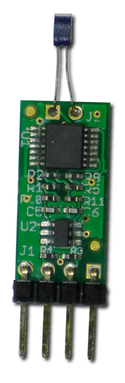
The point of getting the Python V3 interface working was to talk to a temperature sensor (shown at right). The sensor employs a Microchip MCP3421 delta-sigma analogue to digital converter, or ΔΣ ADC.
The device has two different operating modes: a one-shot mode where conversions happen by explicit request; and a continuous mode where conversions happen continuously regardless of whether the data is read out of the device.
ΔΣ converters take longer to perform conversions depending on the resolution being converted. A user can trade speed for precision as required. For the MCP3421, the trade-off is as follows:
| Speed (SPS) | Resolution (bits) |
| 240 | 12 |
| 60 | 14 |
| 15 | 16 |
| 3.75 | 18 |
In the above table, SPS means samples per second. In this case, temperature is a very slow-to-change parameter, so the highest precision comes without much penalty.
The converter also has internal gain scaling (1, 2, 4, or 8:1) , however the analogue circuitry presents voltages that do not need scaling; this is left at 1:1.
Though it’s a common practice in instrumentation to use a Wheatstone Bridge, the extra hardware is a bit large for such a tiny circuit board. Instead, a precision current source is used to drive a Platinum RTD sensor, and a set of amplifiers translate the measured voltage into a differential pair suitable for the ADC.
The MCP3421 is available factory coded to one of eight possible addresses, so up to eight can live on the same I2C bus, from 0x68 to 0x6f.
The device is connected to the expansion header on I2C port #1. In the table below, the pins on the left correspond to J8, the GPIO header of the Raspberry Pi, and the pins on the right correspond to the header on the sensor board.
| r-π – J8 | Signal | Sensor |
| 1 | 3.3V | 1 |
| 3 | SDA | 2 |
| 5 | SCL | 3 |
| 6 | GND | 4 |
Before going any further with software, connect the sensor to the π according to the table above. Since these connections must be made by hand, and there’s no keying on the connector, extra care should be used to ensure the right pins are connected. The image below shows the I2C pins on a π V3 B+. This is an edit to the original post, for clarity; hope it helps!
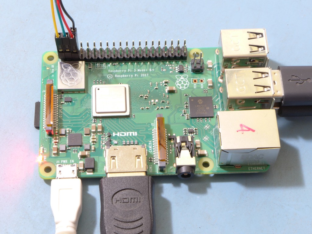
Raspberry Pi 3 B+ with I2C Wiring.
WARNING: Making connections to the GPIO port is at your own risk. If you hook something up backwards or to the wrong pin, you may damage the Rasperry pi and/or the temperature sensor.
An easy point of reference is that pin 1 of J8 has a square solder-pad, and the rest are round. Further, one row of pins is all even numbered, and one is odd. The sensor itself also has a square solder-pad for pin 1.
Back to Python
Picking up where we left off with the Python script, the ΔΣ ADC was initialized but we hadn’t been able to test it out:
#!/usr/bin/python3

import smbus

deltasig = [0x68,0x69,0x6a,0x06b,0x6c,0x6d,0x6e,0x6f] # device addresses
config_byte = 0x1c # continuous mode, 18-bit resolution, gain = 1.

bus = smbus.SMBus(1)
bus.write_byte(deltasig[0],config_byte) # configure the adc
The deltasig = … line specifies each possible address; see hardware description above for more on this. The sensor in this case is addressed at deltasig[0].
The next line is config_byte = 0x1c. This tells the converter how many bits of resolution to use (minimum 12, maximum 18) as well as how much internal gain to apply (1,2,4, or 8:1). The big thing is to sample continuously.
The bus = … line says we want I2C interface #1, not #0.
The last line writes the configuration byte to the MCP3421’s one and only programmable register.
Save the above as a text file; call it test_i2c.py. Next, change the just-saved file’s permissions making it executable; then run it:
...$ chmod 755 test_i2c.py
...$ sudo ./test-i2c.py
Any application needing access to the I2C bus will have to run as root; so, if a ‘permission denied’ message is seen, put a sudo in front of the command for launching the python program as shown above. The result should be free of errors and warnings. If it’s clean, the smbus module has been successfully imported into python3!
Since I2C communication is implemented using the System Management Bus library (smbus), itself a subset of the I2C standard, it has limitations. For one, in the SMB world, each time a device is addressed for reading or writing, the master sends a command byte immediately after the address, something an I2C equipped ADC may not expect. Specifically, the MCP3421 responds to being addressed for reading by transmitting sample data; it doesn’t expect the command byte. The command byte appears to be ignored by the MCP3421.
There are not many functions in the smbus library, but there are a couple that have notable variations in their names: read_block_data vs. read_i2c_block_data; and write_block_data vs. write_i2c_block_data. The read_block_data function can be a problem; see here for details. There is a reference to a kernel panic on the Raspberry Pi, leading to a required power-down to restart the device. Not sure why this is so, but… confirmed! Since there is only one register in the MCP3421, there was no testing of write_block_data vs. write_i2c_block_data.
If the converter is operating in continuous mode, it will continuously update its results registers regardless of whether the data is read out. There is no way of determining if a sample has been missed, but there is a way of determining if a sample has been read: the configuration register’s most significant bit will be set. More on this later.
Setting up a Polling Loop
It’s inefficient to poll continuously, as it hogs the processor’s available bandwidth; instead, a sleep function will be used. sleep() is part of the time module, so add an import time line at the top of the script. Since the register will only update 3.75 times per second, and temperature changes quite slowly for most applications, one sample per second should be more than enough. Also, a loop is required so we can keep polling and updating the results:
#!/usr/bin/python3
# test operation of mcp3421 on i2c bus #1

import smbus
import time

deltasig = [0x68,0x69,0x6a,0x06b,0x6c,0x6d,0x6e,0x6f]           # device addresses
config_byte = 0x1c          # continuous mode, 18-bit resolution, gain = 1.

bus = smbus.SMBus(1)
bus.write_byte(deltasig[0],config_byte) # configure the adc

while True:
    time.sleep(1)
    mcpdata = bus.read_i2c_block_data(deltasig[0],config_byte,4)
    conversionresults = mcpdata[2] + (mcpdata[1] << 8) + (mcpdata[0] << 16)
    print('Conversion results =',hex(conversionresults), 'config-byte:',hex(mcpdata[3]))
Once the device is configured, we enter a while loop which will endlessly read the ADC at 1 second intervals, sleeping between reads. The converter will continue to run while the python program sleeps, so will sample 3.75 times between reads.
The bus.read_i2c_block_data operation reads four bytes from the ADC and places them in an array, mcpdata[]. The format of the data is:
- Byte 0 – D31-24 – SSSSSSSD – sign extended out to 24 bits, 2 MSBs of conversion
- Byte 1 – D23-16 – DDDDDDDD – Conversion data
- Byte 2 – D15-08 – DDDDDDDD – Conversion Data
- Byte 3 – D07-00 – CCCCCCCC – Configuration register contents.
The next line merges the first three bytes into a single 24-bit number. The last new line above prints the data in hexadecimal format. Output looks like this:
Conversion results = 0xff355d config-byte: 0x1c
Conversion results = 0xff355d config-byte: 0x1c
Conversion results = 0xff355d config-byte: 0x1c
Conversion results = 0xff355d config-byte: 0x1c
Conversion results = 0xff355e config-byte: 0x1c
The data looks nice and stable, but a little more work is required to turn it into a meaningful temperature.
The configuration byte shows up as 0x1c in each read. This is good, as it means the data is a new sample each time, that the ADC is running in continuous mode with 18-bits resolution and an internal gain of 1:1.
If the MSB were set, and we saw 0x9c, this would mean the data has not been updated since last being read out. This should never happen because the device is being read much more slowly than it performs conversions: every 1/3.75 or 0.2666 seconds a new sample will be available.
The issue of old data is worth noting, as it’s possible to run multiple instances of the python code and have them all jockeying for access to the I2C device. In this case the ADC will routinely state that data has already been read out, and it’s up to the software to know it waited long enough for a new sample.
Making Raw Data into Temperature
Even though the results are only 18-bits, 24-bits are returned. This is sign extended as far as the ADC is concerned, but to the Raspberry Pi it’s an unsigned number. We want a signed number! To correct it, add the following lines:
    conversionresults = mcpdata[2] + (mcpdata[1] << 8) + (mcpdata[0] << 16)
    conversionresults &= 0x1ffff     # lop off the sign ADC's sign extension
    if mcpdata[0] & 0x80:            # if the data was negative
        conversionresults -= 0x20000 #   subtract off the sign extension bit
Now we have a properly sign-extended result, and can map it to a real temperature:
#!/usr/bin/python3

import smbus
import time

slope = 9.821148E-4      # constants used in mapping temperature
intercept = 7.064956E1

deltasig = [0x68,0x69,0x6a,0x06b,0x6c,0x6d,0x6e,0x6f]           # device addresses
config_byte = 0x1c          # continuous mode, 18-bit resolution, gain = 1.

bus = smbus.SMBus(1)
bus.write_byte(deltasig[0],config_byte) # configure the adc

while True:
    time.sleep(1)
    mcpdata = bus.read_i2c_block_data(deltasig[0],config_byte,4)
    conversionresults = mcpdata[2] + (mcpdata[1] << 8) + (mcpdata[0] << 16)

    conversionresults &= 0x1ffff     # lop off the sign ADC's sign extension
    if mcpdata[0] & 0x80:            # if the data was negative
        conversionresults -= 0x20000     #     subtract off the sign extension bit

    temperature = conversionresults * slope + intercept
    print('Conversion results =',hex(conversionresults), 'config-byte:',hex(mcpdata[3]))
The above code has a couple of constants added: slope, and intercept. The two values are related to the sensor’s resistance and the gain applied by the amplifier circuit. It’s really the resistance of the sensor that varies, but V=IR, and I is fixed; a simple y = mx + b operation will convert voltage (x) to temperature (y), where m = slope, and b = intercept.
Mapping Resistance to Temperature
This is presented for those interested in the temperature sensor itself. For those reading just to get their own I2C devices working, this section can be safely skipped.
Where did the slope and intercept values come from?
The sensing element is a Platinum RTD with a resistance of 1000Ω at 0°C and an approximately linear response to changes in temperature. Here, approximate is a mild understatement; the RTD’s temperature response curve is nearly perfectly linear, and in most cases using a simple algebraic equation to map resistance to temperature is far and away good enough. There are second order variations but they are essentially insignificant.
Gain in the instrumentation amplifier is ~8.284314:1, set by resistor values (0.1% tolerance, very stable over temperature). Common mode voltage (VCM) delivered to the ADC is 1.50V. The ADC itself maps ±2.048V to full span between its differential inputs. With a 3.3V system voltage, VCM=1.5V is quite close to mid span of the supply, and allows each input to swing between 0.476V and 2.524V, the result of which is that the full span of the ADC can be used.
The default gain/offset configuration allows the ΔΣ ADC to convert temperatures between -50°C and +200°C, with converter output becoming positive at approximately 75°C.
Combining the RTD data supplied by the manufacturer with the overall amplifier gain, a slope of 0.0009821148, or 9.821148·10-4 is calculated; a corresponding intercept is obtained at ~70.64956. We’ll skip over exactly how this was done; if curious, a spreadsheet can be supplied showing the arithmetic.
An important detail is the range of linear input of 250°C divided by 218 gives a quantization step size of 953.7·10-6 °C/bit, or slightly better than 1/1000th of a degree per bit. There are not very many applications where this is required. There is always a little noise in the real world; some comes from the Raspberry Pi’s 3.3V power supply, some from stray RF picked up by the RTD’s leads, some Boltzmann noise in the gain resistors and RTD (it’s a resistor after all). The upshot is 1-2 bits of data are lost to noise, or possibly actual temperature variations. Converting noise voltage to noise temperature, variations of ~0.0019°C are not to be trusted. It’s more meaningful, perhaps less distracting, to strip off variations less than about 0.01°C.
Real Temperature at Last!
Changing the print statement into something a bit more meaningful:
    print('Raw:',hex(conversionresults),'- Cooked: %.3f' % temperature,'\b°C',
          '- config-byte:',hex(mcpdata[3]))
Program output now becomes:
Raw: -0xbb1c - Cooked: 23.606°C - config-byte: 0x1c
Raw: -0xbb1c - Cooked: 23.606°C - config-byte: 0x1c
Raw: -0xbb1d - Cooked: 23.605°C - config-byte: 0x1c
Raw: -0xbb1d - Cooked: 23.605°C - config-byte: 0x1c
Raw: -0xbb1d - Cooked: 23.605°C - config-byte: 0x1c
Raw: -0xbb1d - Cooked: 23.605°C - config-byte: 0x1c
Raw: -0xbb1d - Cooked: 23.605°C - config-byte: 0x1c
Raw: -0xbb1c - Cooked: 23.606°C - config-byte: 0x1c
A small amount of converter noise is visible in the above snippet of output data. Stripping off anything smaller than 1/100th of a degree doesn’t give up much information; the extra detail is shown here just for completeness.
And that’s it, only a few lines of code, and a precise measure of temperature. Making the sensor with different I2C addresses is a simple assembly-line swap, so up to eight sensors can be daisy-chained.
The sensor is available for purchase under the following part numbers:
|
|
Each is addressable at 0x68+offset in I2C space. Dimensions are 10x20mm, suitable for mounting in a wide array of enclosures.
Have you tried fm radio module tea5767 with SMBus and Python 3?
We experienced problem sending bytes to the chip. i wonder if you are interested in helping out then co-write an article about it
-have not tried the TEA5767 module, but would like to hear a little more about what you’re trying to do; will e-mail you directly.